
Latest Products


Contact Us
- Wei Four Road, Weizhuang industrial Park, Changyuan District, Xinxiang City, Henan Province, China
- sales@zybc.com
- +86-373-7136666


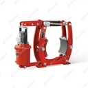
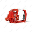
MW800-10000 Series Electromagnetic Drum Brake
Installation and Maintenance Manual for MW800-10000 Series Electromagnetic Drum Brakes The MW800-10000 series electromagnetic drum brake is a core braking component for heavy machinery used in hoisting, metallurgy, mining and other industries. Standardized installation and regular maintenance...
Description
Installation and Maintenance Manual for MW800-10000 Series Electromagnetic Drum Brakes
The MW800-10000 series electromagnetic drum brake is a core braking component for heavy machinery used in hoisting, metallurgy, mining and other industries. Standardized installation and regular maintenance are critical to ensuring its braking performance, extending service life and preventing safety accidents. All operations must comply with equipment safety regulations. The power supply must be disconnected and proper safety protection measures taken. Live working is strictly prohibited.
1. Pre-installation Preparation
Verify Equipment and Spare PartsCheck against the equipment packing list to ensure the brake body, DT-800 electromagnet, brake linings, fasteners and installation accessories are complete. Verify that the model is MW800-10000 and confirm there is no damage, deformation or cracking caused during transportation. Prepare special tools such as a torque wrench, spirit level, feeler gauge, lubricating oil and cleaning tools.
Clean the Installation SiteThoroughly remove oil, rust, dust and debris from the brake mounting base and the surface of the brake drum. Inspect the runout and wear of the brake drum. If the values exceed the allowable limits specified by the manufacturer, repair or replace the brake drum first to avoid compromising braking effectiveness.
Confirm Installation ConditionsEnsure the installation environment meets the equipment requirements: ambient temperature ranging from -25℃ to +50℃, relative humidity ≤ 90%, and altitude not exceeding 1000 meters. The power cable specifications must match the rated parameters of the brake, and a reliable grounding device must be provided. For explosion-proof applications, additional compliance with explosion-proof installation codes is required.
2. Core Installation Procedures
2.1 Base Mounting and Fixing
Hoist the brake to the preset installation position. Use a spirit level to calibrate the levelness and verticality of the brake, ensuring the centerlines of the brake and the brake drum are aligned to prevent uneven wear.
Secure the brake base using high-strength bolts, tightened to the torque value specified in the equipment manual. Ordinary bolts must not be used as substitutes for dedicated fasteners. Recheck the tightness of all bolts after installation to prevent loosening during operation.
Adjust the brake's mounting position to achieve uniform contact between the brake linings and the brake drum. Keep the deviation of the single-side fitting clearance within the allowable range specified by the manufacturer.
2.2 Installation of Electromagnet and Actuator
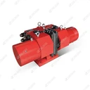
Install the DT-800 electromagnet, ensuring the iron core moves smoothly without jamming. Apply the specified grease to the connecting pins and joint bearings to guarantee flexible operation.
Connect the pull rod and spring assembly of the electromagnet, and adjust the preload of the brake springs. Spring preload directly determines the braking torque and must be adjusted strictly in accordance with the manual parameters. Arbitrarily increasing or reducing the preload is strictly forbidden.
Rotate the brake drum manually to check for interference between the brake arms, linings and the drum. Ensure the brake linings fit tightly against the drum when de-energized, and can fully release when energized.
2.3 Electrical Wiring
Completely disconnect the upstream power supply and attach a warning tag to prevent accidental energization.
Wire in accordance with the electrical schematic diagram. Separate the control circuits from the main circuits, and fasten all wiring terminals securely to avoid loose connections and short circuits. For explosion-proof brake models, the junction box must be properly sealed; explosion-proof surfaces must not be damaged, and sealing gaskets must be intact and undamaged.
Complete the grounding connection, ensuring the grounding resistance complies with electrical safety codes. After wiring, use a multimeter to check circuit continuity and insulation resistance. Restore power only after confirming everything is correct.
2.4 Testing and Trial Operation
No-load inching test: Apply power briefly to observe whether the electromagnet engages and releases smoothly, whether the brake arms move synchronously, and whether there is abnormal noise or jamming.
Clearance adjustment: Measure the release clearance between the brake linings and the brake drum using a feeler gauge. The rated release clearance for the MW800-10000 series is 1.25 mm. An excessively large clearance causes delayed braking response, while an excessively small one leads to brake dragging, overheating and accelerated wear. Precisely adjust the clearance via adjusting bolts to ensure consistent clearance on both sides.
Load trial operation: Apply the rated load gradually to test braking performance. Check whether the braking torque meets the standard, whether braking is smooth, and whether there are unusual odors or abnormal temperature rises. After several consecutive trial runs and confirmation that all components function properly, the brake can be put into formal operation.
3. Routine Maintenance Specifications
Routine maintenance focuses on inspection, cleaning and tightening, and is recommended before and after each shift.
Visual and Operational InspectionInspect the brake housing and brake arms for deformation or cracks. Check the junction box and electromagnet for water or dust ingress. Monitor operating noise; the engagement and release of the brake should be free of sharp abnormal noises or impact sounds.
Cleaning OperationsUse dry compressed air or a clean cloth to remove dust and oil from the brake surface, brake drum and brake linings. Direct water washing of electrical components is strictly prohibited to prevent short circuits and insulation failure.
Recheck Fasteners and ClearanceInspect base bolts, electromagnet connecting bolts and pin nuts for looseness, and tighten them to the specified torque promptly. Check the brake clearance daily. Readjust immediately if braking delay or increased braking distance occurs.
4. Scheduled Maintenance and Overhaul Specifications
It is recommended to formulate a weekly, monthly and annual maintenance plan based on equipment usage frequency and operating environment. The maintenance interval should be shortened for heavy-duty, high-dust or high-humidity environments.
4.1 Weekly Maintenance
Reinspect the wear condition of the brake linings and record the wear thickness.
Inspect lubrication points, and replenish grease to pins and joint bearings to maintain flexible movement of moving parts.
Check electrical circuits for damaged insulation layers, and inspect terminals for ablation or overheating.
4.2 Monthly Maintenance
Disassemble and inspect the brake linings: If the linings are worn to the wear limit mark, or suffer from uneven wear, cracking or delamination, they must be replaced as a complete set. Continued use is prohibited. Use only original-equivalent linings of the same specification to ensure matching friction coefficient and dimensions.
Inspect the brake drum: Measure the wear and runout of the drum's working surface. Perform turning repair or replacement if the values exceed limits. Clean grooves and oil contamination on the drum surface.
Test the electromagnet: Measure the core stroke and attraction force, and inspect the coil insulation resistance. Repair or replace the electromagnet promptly if coil insulation aging, core jamming or insufficient attraction force is detected.
Inspect the brake springs: Check for deformation, cracking or elastic fatigue. Replace springs immediately if they fail to meet technical parameters, to avoid insufficient braking torque.
4.3 Annual Overhaul
Completely disassemble the brake, and conduct non-destructive testing and performance testing on all moving parts, springs, pins and bearings.
Replace all aged seals and lubricating grease. Repair or replace mechanical components with excessive wear.
Conduct a comprehensive inspection of the electrical system, including circuits, coils and grounding systems, and perform withstand voltage and insulation tests.
Recalibrate the brake clearance and spring preload. Complete full-process no-load and load testing, issue an overhaul report, and archive all records.
5. Common Faults and Emergency Troubleshooting
| Fault Phenomenon | Common Causes | Solutions |
|---|---|---|
| Brake failure, insufficient braking force | Severe wear of brake linings; spring failure; incomplete engagement of electromagnet; excessive oil contamination on brake drum | Replace brake linings and springs; overhaul the electromagnet; clean oil contamination on the brake drum and readjust the clearance |
| Brake dragging, abnormal overheating | Insufficient release clearance; electromagnet release failure; jamming of connecting pins | Readjust the brake clearance; overhaul the electromagnet coil and iron core; lubricate and repair connecting pins |
| Abnormal noise and overheating during electromagnet engagement | Dirty or deformed core contact surfaces; short circuit or loose connection of coil; abnormal voltage | Clean and repair the iron core; check circuits and voltage, repair or replace the coil |
| Loose fasteners, component displacement | Bolt loosening caused by vibration; unqualified installation torque | Stop the machine and tighten bolts, recheck to the standard torque, and install anti-loosening devices if necessary |
6. Safety Precautions
All installation, overhaul and maintenance operations must be performed by certified professional electrical and mechanical maintenance personnel. Unauthorized personnel are strictly prohibited from operating the equipment.
The power disconnection, voltage testing, warning tagging and locking procedure must be implemented before maintenance, and a safety supervisor must be assigned.
Only original or standard-compliant replacement parts can be used for spare parts replacement. Non-standard parts are prohibited to avoid compromising braking performance and explosion-proof performance (for explosion-proof models).
Establish a maintenance and overhaul log to record installation and commissioning data, maintenance time, replaced spare parts, and fault handling details, to facilitate traceability and equipment condition prediction.
If the equipment develops unresolved faults or critical components are severely damaged, stop operation immediately, and contact the manufacturer's technical personnel for repair.
Hot Tags: mw800-10000 series electromagnetic drum brake, China, manufacturers, supplier, factory, customized, Electromagnetic drum braking, Environmental Electromagnetic drum brake, High frequency Electromagnetic drum brake, No asbestos liner Electromagnetic drum brake, No noise Electromagnetic drum brake, smooth Electromagnetic drum brake
You Might Also Like


