Latest Products


Contact Us
- Wei Four Road, Weizhuang industrial Park, Changyuan District, Xinxiang City, Henan Province, China
- sales@zybc.com
- +86-373-7136666
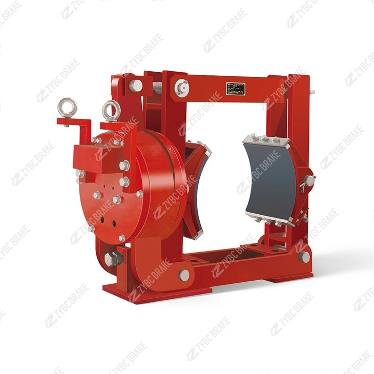


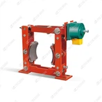
ZWZB-500/400 Series Electromagnetic Drum Brakes
ZWZB - 500/400 is a DC - powered, normally - closed electromagnetic drum brake, a replacement for ZWZ3/ZWZ3A series, designed for DC - driven industrial machinery braking. Below are its core details: Core Technical Parameters Operating Conditions Ambient temperature: -20°C to +40°C (some...
Description
ZWZB - 500/400 is a DC - powered, normally - closed electromagnetic drum brake, a replacement for ZWZ3/ZWZ3A series, designed for DC - driven industrial machinery braking. Below are its core details:
Core Technical Parameters
| Parameter | Value |
|---|---|
| Model | ZWZB - 500/400 |
| Applicable drum diameter | 500 mm |
| Rated braking torque | 400 N·m |
| Power supply | DC 110V/220V (control circuit AC 380V, 50Hz) |
| Matched electromagnet | DC electromagnet (rated suction force varies by manufacturer, typically matched to 400 N·m torque demand) |
| Brake shoe retraction distance | 0.6-0.8 mm |
| Operating frequency | ≤720 cycles/h (S3 - 25%, 40%, 60% duty cycle) |
| Total weight | About 85-95 kg (subject to manufacturer's configuration) |
| Compliance standards | GB 6334-86 (dimensions/torque), JB/T7685-2006 (technical requirements) |
| Key installation dimension (typical) | Overall length approx. 850 mm, installation hole center distance approx. 450 mm, mounting height approx. 900 mm |
Operating Conditions
Ambient temperature: -20°C to +40°C (some manufacturers extend to -25°C to +50°C).
Relative humidity: ≤90% (non - condensing).
Altitude: ≤2000 m.
Environment: No flammable, explosive, corrosive gases or conductive dust; outdoor/corrosive environments require anti - corrosion modification.
Structural & Performance Features
Fail - safe normally - closed design: Spring - applied braking when power - off, electromagnetic release when powered on, ensuring load safety during power outages.
DC - driven efficiency: Dedicated for DC - powered equipment; stable release, low heat generation, and high transmission efficiency at hinge points with self - lubricating bearings.
Eco - friendly & durable: Non - asbestos brake linings; reliable performance, low noise, and adjustable gap for easy maintenance.
Replacement compatibility: Consistent with ZWZ3 series installation dimensions for seamless upgrades.
Typical Applications
Suitable for deceleration and parking braking of DC - driven cranes, winches, metallurgical machinery, and port loading/unloading equipment, meeting medium - load, moderate - frequency braking needs.
Installing the ZWZB - 500/400 normally - closed electromagnetic drum brake requires strict adherence to safety procedures, precise mechanical positioning, electrical connection, and gap adjustment to ensure reliable operation. Below is a step - by - step installation guide:
Pre - Installation Preparation
Safety & Inspection
Cut off the power supply of the equipment and hang a warning sign. Wear protective gear such as gloves and goggles.
Check if the brake components (braking spring, electromagnet, brake shoe, non - asbestos lining, self - lubricating bearing) are intact, without cracks, deformation, or excessive wear. Ensure the matching 500mm brake drum has no scratches, out - of - roundness, or oil stains.
Confirm that the mounting base and bolt holes meet the requirements of the ZWZB - 500/400 installation dimensions (installation hole center distance is about 450mm), and clean the mounting surface to remove oil stains, rust, and burrs.
Tool & Accessory Preparation
Prepare torque wrench, feeler gauge (0.6-0.8mm), level, shim, open - end wrench, and electrical insulation tools.
Check that accessories such as fixing bolts, cotter pins, equal - retraction springs, and manual release levers are complete.
Mechanical Installation Steps
Mounting Base Fixing
Place the brake base on the pre - installed bracket, align the mounting holes, and use matching high - strength bolts to fix it initially (do not fully tighten yet). Use a level to ensure the base is horizontal, and add shims under the base if necessary for adjustment.
Tighten the mounting bolts diagonally and in stages to the specified torque (usually 8.8 - grade bolts with a torque of 80-100 N·m, subject to the manufacturer's manual).
Brake Body Assembly
For side - mounted installation, remove the pin connecting the base and the brake arm, swing the brake arm upward, push the brake to the position where the brake shoe is aligned with the 500mm drum, and then reset the brake arm.
Reinstall the equal - retraction spring, the connecting pin, and secure it with a cotter pin. Ensure the hinge points of the brake arm are flexible without jamming.
Install the manual release mechanism, and test that the release operation is smooth and can lock in place.
Position Calibration
Adjust the position of the brake so that the cylindrical surface of the brake shoe is parallel to the axis of the brake drum, and the gap between the two sides of the drum is uniform. The coaxiality deviation should not exceed 0.2mm.
Electrical Connection
Connect the DC electromagnet coil to the DC 110V/220V power supply (the control circuit uses AC 380V, 50Hz). Follow the wiring diagram, distinguish the positive and negative poles, and connect the wires firmly.
Use heat - shrinkable tubes or insulation tape to insulate the joints to prevent short circuits caused by moisture and oil pollution. Install a surge protector and a thermal relay in the circuit to protect the electromagnet.
Check the insulation resistance of the coil with a megger; it should be ≥1MΩ at room temperature to ensure electrical safety.
Gap Adjustment & Commissioning
Gap Setting
When the power is off, the brake is in the braking state. Loosen the adjusting nut on the brake arm, and when the power is on (the electromagnet is energized and released), use a 0.6-0.8mm feeler gauge to adjust the retraction gap of the brake shoe. Ensure the gaps on both sides of the brake drum are equal and within the range of 0.6-0.8mm.
Tighten the lock nut after adjustment to prevent loosening during operation.
Functional Test
Power on and test the release action. The electromagnet should pull in smoothly, and the brake shoe should retract completely without dragging the drum. The response time should be ≤0.5s.
Power off to test the braking effect. The brake should quickly hold the drum under the action of the spring force, with a rated braking torque of 400N·m, no abnormal noise, and stable braking.
Test the manual release function again to ensure it can release the brake reliably when the power is off.
Continuous Operation Test
Run at the rated frequency (≤720 cycles/h), check for overheating of the electromagnet (the surface temperature should not exceed 80°C), and confirm that the braking torque and action consistency meet the requirements.
Post - Installation Inspection & Maintenance Tips
After installation, recheck the bolt tightness, gap size, and electrical insulation.
Regularly check the wear of the brake lining (replace when the thickness is less than 5mm), the elasticity of the spring, and the lubrication of the hinge points.
For outdoor or corrosive environments, use anti - corrosion modified parts and regularly clean the brake surface.
Hot Tags: zwzb-500/400 series electromagnetic drum brakes, China, manufacturers, supplier, factory, customized, Electromagnetic drum braking, Environmental Electromagnetic drum brake, High frequency Electromagnetic drum brake, No asbestos liner Electromagnetic drum brake, No noise Electromagnetic drum brake, smooth Electromagnetic drum brake
You Might Also Like