
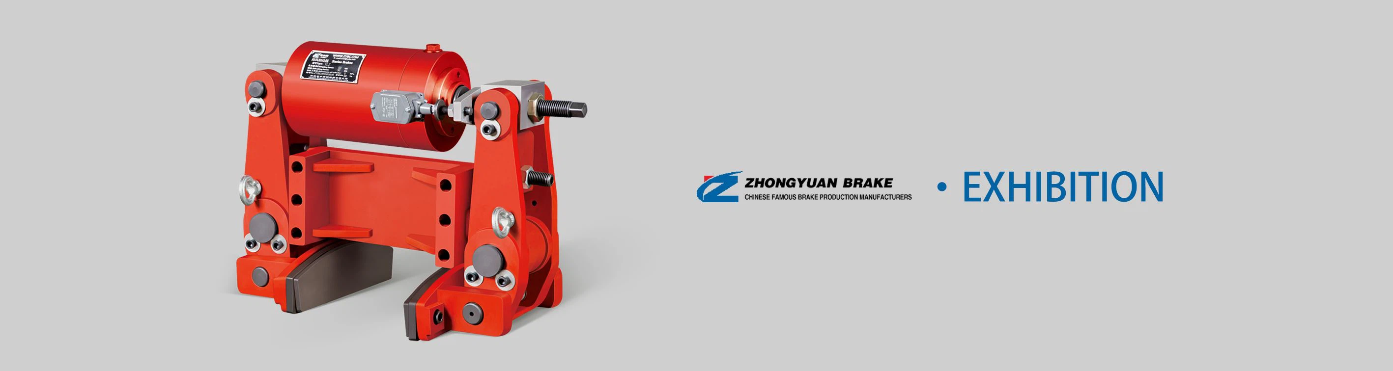
Key Components
1 Pneumatic Actuator
- Cylinder Assembly: The core of the pneumatic actuator is a high - pressure cylinder made of durable materials such as aluminum alloy or stainless steel. It is designed to withstand the operating pressures typically encountered in pneumatic systems, which can range from 6 to 10 bar in most applications. The cylinder has a precisely machined bore and piston to ensure smooth movement and minimal friction.
- Piston and Rod: The piston is connected to a sturdy piston rod. The piston divides the cylinder into two chambers, and the application of compressed air to one of the chambers causes the piston to move linearly, which in turn actuates the braking mechanism. The piston rod is made of hardened steel to resist bending and wear during repeated operations.
- Seals: High - quality seals are installed at various points in the cylinder, including around the piston and piston rod. These seals prevent air leakage, ensuring efficient power transmission and maintaining the required braking force. They are made of materials such as nitrile rubber or polyurethane, which offer good resistance to air pressure, temperature variations, and chemical exposure.
2 Disc Brake Assembly
- Brake Disc: The brake disc is a flat, circular component typically made of cast iron or a high - strength composite material. It is mounted on the rotating shaft of the equipment to be braked. The disc has a smooth surface finish to minimize friction and wear during normal operation and to ensure consistent braking performance. The diameter of the disc is carefully selected based on the torque requirements of the application, with larger diameters providing greater braking force.
- Brake Pads: The brake pads are the friction - generating elements of the disc brake. They are made of a composite material that contains friction - enhancing substances such as asbestos - free organic compounds, metallic particles, or ceramic fibers. The pads are mounted on a caliper assembly and are designed to press against the brake disc when the braking mechanism is actuated. The shape and size of the pads are optimized to provide even pressure distribution across the disc surface, reducing wear and improving braking efficiency.
- Caliper Assembly: The caliper houses the brake pads and is responsible for applying the clamping force to the disc. It is typically made of cast iron or aluminum alloy for strength and rigidity. The caliper can be of a floating or fixed design. In a floating caliper, the caliper body can move laterally, allowing the pads to contact the disc evenly from both sides. In a fixed caliper, the pads are moved independently by hydraulic or pneumatic pistons to press against the disc. The CQPD25.4B model may use a specific caliper design based on its intended application and performance requirements.
3 Control Valves
- Directional Control Valve: This valve is used to control the direction of compressed air flow to the pneumatic actuator. It can be a 2/2 (two - port, two - position) or 3/2 (three - port, two - position) valve, depending on the complexity of the braking system. The valve is operated either manually, electrically (using solenoids), or pneumatically. When activated, it directs compressed air to the appropriate chamber of the cylinder, causing the piston to move and actuate the brakes.
- Pressure Regulating Valve: To ensure consistent braking performance, a pressure regulating valve is often included in the system. This valve maintains a constant output pressure regardless of fluctuations in the input air pressure. It can be adjusted to set the desired braking force, allowing for fine - tuning of the braking mechanism according to the specific requirements of the application.


