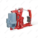
The TYW-400 series foot-operated hydraulic drum brake is a manually controlled, hydraulically actuated drum brake designed for low-to-medium load industrial equipment that requires simple, intuitive braking operation. It is widely used in scenarios where manual intervention (e.g., foot control) is preferred, such as small cranes, workshop trolleys, and light-duty conveyors. Below is a detailed overview of its core parameters, structural features, working principle, applications, and maintenance guidelines:
Core Technical Parameters
| Parameter | Details |
|---|---|
| Applicable drum diameter | 400 mm (matches the "400" in the model name) |
| Rated braking torque | 300–600 N·m (adjustable via hydraulic pressure and spring force) |
| Hydraulic system pressure | 2–5 MPa (generated by foot pedal actuation) |
| Brake shoe clearance | 0.8–1.2 mm (manual adjustment via clearance screw) |
| Brake lining specification | Non-asbestos semi-metallic lining, thickness 12 mm (replace when ≤3 mm) |
| Foot pedal stroke | 150–200 mm (adjustable for operator comfort) |
| Oil type | ISO VG 32/46 hydraulic oil (for the integrated hydraulic cylinder) |
| Operating environment | Ambient temperature: -20°C to +50°C; Relative humidity: ≤90% |
| Total weight | ~65–75 kg (includes brake body and foot hydraulic pedal unit) |
| Compliance standards | JB/T 6406-2006 (drum brake technical requirements), GB/T 3811-2008 (crane design standards) |
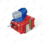
Structural & Design Features
Integrated Foot-Hydraulic Control System
The brake consists of two key parts: the drum brake body (mounted on the equipment) and the foot-operated hydraulic pedal unit (installed near the operator's position, connected via a high-pressure hydraulic hose).
The pedal unit includes a small hydraulic pump, a pressure relief valve, and a return spring-eliminating the need for external power sources (e.g., electricity or compressed air).
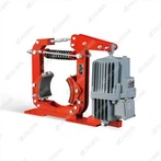
Fail-Safe Auxiliary Spring Design
While primarily foot-hydraulically actuated, it is equipped with a secondary return spring for emergency braking. If the hydraulic system fails (e.g., hose rupture), the spring will drive the brake shoes to clamp the drum, preventing load slippage.
Adjustable Braking Force
The braking torque can be adjusted in two ways:
Hydraulic pressure adjustment: Rotate the pressure relief valve on the pedal unit to change the maximum hydraulic pressure (higher pressure = larger braking torque).
Mechanical adjustment: Adjust the tension of the auxiliary spring via the adjusting nut on the brake body for fine-tuning.
Durable & Low-Maintenance Structure
Main hinge points are equipped with self-lubricating bearings to reduce wear and avoid frequent lubrication.
Brake linings use a clip-on design for quick replacement without disassembling the entire brake body.
The hydraulic cylinder features a sealed structure to prevent oil leakage and dust ingress.
Working Principle
The TYW-400 operates on a hydraulically released, spring-auxiliary braking principle (reverse of most power-driven brakes), tailored for manual control:
Normal Operation (Release State)
When the operator presses the foot pedal, the integrated hydraulic pump generates pressure, which is transmitted through the hydraulic hose to the brake's hydraulic cylinder.
The hydraulic cylinder pushes the brake arms apart, retracting the brake shoes from the drum-releasing the brake and allowing the equipment to run.
Braking State
When the operator releases the foot pedal, the hydraulic pressure drops. The return spring in the pedal unit resets the pump, and the brake's auxiliary spring drives the brake shoes to clamp the drum, achieving braking.
For emergency braking: The operator can press the pedal harder to increase hydraulic pressure temporarily, or the auxiliary spring will activate automatically if the hydraulic system fails.
Parking Braking
A locking pin is provided on the foot pedal. After braking, the pin can be engaged to lock the pedal in the released position (for long-term parking, preventing accidental actuation).