YWZ9 Series
Electro Hydraulic Drum Brake
Operation Manual
![]()
Henan Zhongyuan Brake Co., Ltd
Date:20120405
目录
一、Important Information……………………………………………(1)
1.1safety instruction………………………………………………(1)
1.2Lminted guarantee liability …………………………………(1)
二、Introduction………………………………………………………(2)
三、Working condition…………………………………………………(2)
四、Structure and working principle…………………………………(2)
五、Brake Installation and Adjustment………………………………(2)
5.1 Inspection before installation…………………………………(2)
5.2 Installation and Adjustment…………………………………(4)
六、Brake use and maintenance………………………………………(6)
6.1 Brake Use ………………………………………………(6)
6.2 Maintenance …………………………………………… (7)
6.3 Inspection during use…………………………………………(7)
七、Inspection during Use …………………………………………(8)
一、Important Information
1.1 Safety instructions
Electric hydraulic drum brake (the brake) is a device that decelerates and / or stops braking on the brake wheel through brake tiles (friction liner). During braking, the mechanical energy of the moving object is absorbed and dissipated around by converting into heat on the friction subsurface.
The necessary premise for the normal operation of the brake are: 1. Relevant components applied on the friction liner and passed to the brake wheel operate normally; 2. The brake overlay pressure, friction coefficient between the friction liner and the brake wheel are within the design value range. Any premise can not be satisfied, the brake will be unable to work properly and the failure leads to the equipment partially or completely out of control causing the load to fall freely, and / or cause harm to people, or even the loss of life!
In order to ensure the proper operation of the brake and avoid personal injury accidents, the brake design selection and operation and maintenance shall remember and fully understand and observe the following principles and requirements (not limited to this):
The newly installed brake (or liner) that is not fully run and engaged may have half or less of the rated torque because the brake pad does not fit well to the rated wheel;
The brake torque used for the main lifting or similar mechanism shall be at least more than twice the actual load moment on the brake shaft;
Carefully read, understand the contents of this manual, and strictly observe the methods and steps of this manual before installing, using or maintaining the brakes;
Do not adjust the brake spring at will, to ensure that the brake brake torque is consistent with the design requirements;
No oil, paint, grease or other impurities shall be allowed to adhere, sputter on the brake wheel and / or the brake surfaces of the brake liner;
In the brake working state, do not touch the brake wheel, brake liner and adjacent components to burn the skin; do not touch or approach the rotating brake wheel, coupling and / or coupling; do not allow the object to fall on the rotating brake wheel to prevent centrifugal force; cover the ownership disk and coupling as much as possible;
Do not use the manual release lever to open the brake (see manual 6.2);
Do not access or enter the lower area of the lifting goods, to prevent sudden brake failure and causing injury to person or life;
Use only the spare parts approved by the Company or the Company;
Do not have the brake signs and warning signs covered with paint or other dirt.
1.2 Limited guarantee liability
The Company guarantees that the design, manufacture, the materials, and process within one year affecting its function and use. During the warranty period, the Company has the responsibility to replace or repair any product tested and tested to be returned by the user to the Company or the authorized service station and to maintain its integrity. In addition, the Company makes no other express or implied warranty, including (but not limited to) the design, status or process of the product and an implied warranty consistent with the specific purpose of use.
As permitted by relevant law, for any special, indirect, accidental or incidental damages (including, but not limited to, transportation expenses, loss of profit
二、Introduction
YWZ9(5), YWZ9-A (instead of the original YWZ13 model) series electric hydraulic drum brakes (hereinafter brakes) for use in three-phase AC, frequency 50HZ, of 380V or (60HZ, 460V) (special circumstances shall be specified at order). It is mainly used for deceleration and parking braking of various mechanisms in lifting, belt transportation, port loading and unloading and metallurgy machinery。
三、Working Condition:
3.1 Ambient temperature: -25 ℃ ~ + 50 ℃ (see the pusher operating instructions when below-25 ℃);
3.2 No flammable, explosive and corrosive gases in the surrounding working environment, and the air relative humidity is not more than 90%;
3.3 Elevation of the use site in accordance with GB755-2000.
3.4 See the pusher nameplate for the power supply voltage.
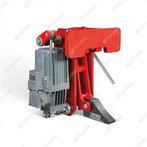
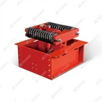
四、Structure and working principle:
The YWZ9(5), YWZ9-A series electric hydraulic drum brake consists of two parts of the brake frame and the matching ED series electric hydraulic pusher. The principle works as follows: when the mechanism is powered off, When you have stopped working, Brake the brake-the is also powered off (or delayed delay), Stop the drive (thrust elimination), The spring force of the brake spring is transmitted to the brake tile through both brake arms, To generate the specified pressure on the brake cover, And establish the specified braking torque, Brakes braking; When the mechanism is powered on to drive, The brake pusher also energizes the drive and quickly generates enough thrust to push the lever, Forced the brake spring for further compression, Brake arm opens outward to both sides, Remove the brake tile block brake cover from the brake wheel, Eliminate pressure and brake moment of brake over, Stop the brake action.
Various limit (interlock) switches can be added as required by the user. He was often necessary for modern lifting transportation and efficient loading and unloading equipment. The function of the limit switch gives the driver room (control room) or PLC control certain specific monitoring (fault display) or interlocking protection signals of the brake.
The brake may also add a manual release device and its safety interlocking switch as required, when the power grid is powered off due to failure or other reasons, the brake is required to open the brake, and can be loosened and controlled by the manual release device.
五、Brake Installation and Adjustment
The brake shall be installed correctly, otherwise it will affect the normal use of the brake, so please strictly follow the methods and steps in this manual. For our assistance or assistance for your installation, please contact our Sales and Service Department.
5.1Inspection before the installation:
Inspection of the 5.1.1 brakes:
Are the parts of the a. brake complete;
Whether the b. brake operation is sensitive;
Whether the friction surface of the c. brake pad is covered with oil pollution, paint and other impurities affecting the friction force.
d. Core treated brakes, selection (including supply voltage, frequency and pusher model) and requirements.
If the above is found to fail, the installation must be started after the processing is resolved.
5.1.2 Brake wheel inspection:
a. brake wheel shall not have rust, oil stain and nonsmoothness defects on the surface. It is strictly forbidden to use brake wheels with existing cracks or other serious defects;
When b. brake wheel rotates around the axis, its radial beating out: at wheel diameter ≤ 250, not greater than ≤ 500 <, not greater than 0.12,500 <≤ 800, not greater than 0.15;
c. brake wheel surface roughness of 3.2, too rough or smooth can different braking performance.
5.1.3 Construction and inspection of the brake installation base:
The mounting base of the a. brake shall be stable and flat, and the mounting hole position size shall be accurate;
b. If the brake mounting base is installed with the brake, secure the (welded or bolted) base and the brake are in place;
c. If the brake mounting base has not been processed with the mounting hole, the brake shall be drilled with the mounting hole and then fix the brake;
The relative position tolerance of the mounting base and hole position of the brake base (see Figure 1) shall not exceed those specified in Table 1。
![]()
![]()
![]()
5.2 Installation and adjustment
5.2.1Before installing the brake, determine which side of the brake repair and adjustment space (i. e. large space or considered
Easy working side). If the tile block along with the position adjustment device 13 and the pitch equalization device 16 are not on the service space side, it may be removed on the same side。
5.2.2Refer to (Figure 2) for brake installation as following the following regulations and steps:
Vertical installation: first rotate the spring pull rod (6) to minimize the brake spring force, and then turn the pull rod (10) to open the two brake arms, and then set the brake on the brake wheel;
Cross installation: when the brake wheel has been installed between the motor or other components, first remove the nut on the back of the bolt (14), remove it from the distance equalization device (16), then hit the pin shaft (15), lift the brake arm (11) upward, from the side door to the brake wheel, and reinstall the above removed parts after installation.
After the brake is placed on the main machine base, loosen the anchor bolt and rotate the pull rod (10). Then the adjustment bolt in the tile block adjustment device (13) shall separate from the brake shoe to fit the brake tiles to the brake wheel. If it is not fit, continue to rotate the pull rod (10). When the brake shoe fits to the brake wheel surface, stop the rotation, and then tighten the anchor bolts.
Open the pusher junction box cover and connect the pusher power cord and ground wire as specified. After connecting the wire, cover the junction box cover and tighten the fixing screws.
The supporting ED series promoters have been used directly before leaving the factory. (If the user needs to fill the oil or replace the hydraulic oil, please refer to the operating instructions of the company promoter. )
5.2.3 Brake adjustment
Working travel adjustment for the a. driver:
The spring force shall be released to a minimum, then rotate the lever (10) to keep the brake closed and continue rotating, when the pusher rises slowly to reach the rise height H1 (Table 2.1 or 2.2) rating. As the brake liner wears out, the working travel gradually increases and the H1 value gradually decreases. When reduced to the minimum value (see Table 2.1 or 2.2), readjust the above method, otherwise the braking effect is lost.
Adjustment of the b. brake moment:
Rotate the spring rod (6) to compress the spring and align the upper edge of the spring lower seat along the desired brake torque value.
c. tile with adjustment:
When the brake is in the lock state, rotate the bolt in the position adjustment device (13) that the top in gently contact with the brake tile bar plate and tighten the nut.
Adjustment of the d. equidistant device: first loosen the bolt (14), hold the brake, and then tighten the bolt (14).
The series of brakes can be fitted with the following accessories, adjusted as follows:
Adjustment of e. compensation mechanism: after the thruster is energized, the pusher reaches the working travel position, and the paddle (9) rotates upward under the corresponding lever hole drive, the pusher is powered off and then returns to the initial position (the H1 rating) height, then the arc surface of the adjustment plate (8) will contact the paddle (9), and then tighten the adjustment screw (7).
f. Manual Device Adjustment:
When the pusher is not working, the brake can be opened (for outage maintenance) by pulling the manual device (19).
g. display device:
Use to display the operating status of the brake, please connect the parameter of the travel switch nameplate to adjust the crash plate (18) so that the travel switch can correctly display the operating status of the brake。
*Table 2.1 Unit:mm
Type | H1(mm) | D | A | d | E | H | n | ||
Brake type | Thruster Type | value | Min value | ||||||
YWZ9(5)-160/E23 | ED-23/5 | 10 | 5 | 160 | 430 | 14 | 145 | 400 | 8 |
YWZ9(5)-200/E23 | ED-23/5 | 10 | 5 | 200 | 470 | 14 | 175 | 500 | 10 |
YWZ9(5)-200/E30 | ED-30/5 | 10 | 5 | 200 | 470 | 14 | 175 | 500 | 10 |
YWZ9(5)-250/E30 | ED-30/5 | 10 | 5 | 250 | 535 | 18 | 205 | 585 | 12 |
YWZ9(5)-250/E50 | ED-50/6 | 15 | 5 | 250 | 575 | 18 | 205 | 585 | 12 |
YWZ9(5)-300/E30 | ED-30/5 | 10 | 5 | 300 | 590 | 18 | 255 | 585 | 12 |
YWZ9(5)-300/E50 | ED-50/6 | 15 | 5 | 300 | 630 | 18 | 255 | 585 | 12 |
YWZ9(5)-300/E80 | ED-80/6 | 15 | 5 | 300 | 630 | 18 | 255 | 585 | 12 |
YWZ9(5)-315/E30 | ED-30/5 | 10 | 5 | 315 | 590 | 18 | 255 | 585 | 12 |
YWZ9(5)-315/E50 | ED-50/6 | 15 | 5 | 315 | 630 | 18 | 255 | 585 | 12 |
YWZ9(5)-315/E80 | ED-80/6 | 15 | 5 | 315 | 630 | 18 | 255 | 585 | 12 |
YWZ9(5)-400/E50 | ED-50/6 | 15 | 5 | 400 | 710 | 22 | 310 | 715 | 14 |
YWZ9(5)-400/E80 | ED-80/6 | 15 | 5 | 400 | 710 | 22 | 310 | 775 | 14 |
YWZ9(5)-400/E121 | ED-121/6 | 15 | 5 | 400 | 700 | 22 | 310 | 775 | 14 |
YWZ9(5)-500/E80 | ED-80/6 | 15 | 5 | 500 | 810 | 22 | 390 | 840 | 16 |
YWZ9(5)-500/E121 | ED-121/6 | 15 | 5 | 500 | 800 | 22 | 390 | 840 | 16 |
YWZ9(5)-500/E201 | ED-201/6 | 15 | 5 | 500 | 800 | 22 | 390 | 840 | 16 |
YWZ9(5)-500/E201/12 | ED-201/12 | 35 | 5 | 500 | 800 | 22 | 390 | 840 | 16 |
YWZ9(5)-500/E301 | ED-301/6 | 15 | 5 | 500 | 800 | 22 | 390 | 840 | 16 |
YWZ9(5)-600/E121 | ED-121/6 | 15 | 5 | 600 | 925 | 27 | 470 | 1025 | 25 |
YWZ9(5)-600/E201 | ED-201/6 | 15 | 5 | 600 | 925 | 27 | 470 | 1025 | 25 |
YWZ9(5)-600/E301 | ED-301/6 | 15 | 5 | 600 | 925 | 27 | 470 | 1025 | 25 |
YWZ9(5)-600/E301/12 | ED-301/12 | 35 | 5 | 600 | 925 | 27 | 470 | 1025 | 25 |
YWZ9(5)-630/E121 | ED-121/6 | 15 | 5 | 630 | 925 | 27 | 470 | 1025 | 25 |
YWZ9(5)-630/E201 | ED-201/6 | 15 | 5 | 630 | 925 | 27 | 470 | 1025 | 25 |
YWZ9(5)-630/E301 | ED-301/6 | 15 | 5 | 630 | 925 | 27 | 470 | 1025 | 25 |
YWZ9(5)-630/E301/12 | ED-301/12 | 35 | 5 | 630 | 925 | 27 | 470 | 1025 | 25 |
YWZ9(5)-700/E201 | ED-201/6 | 15 | 5 | 700 | 980 | 27 | 530 | 1135 | 30 |
YWZ9(5)-700/E301 | ED-301/6 | 15 | 5 | 700 | 980 | 27 | 530 | 1135 | 30 |
YWZ9(5)-710/E201 | ED-201/6 | 15 | 5 | 710 | 980 | 27 | 530 | 1135 | 30 |
YWZ9(5)-710/E301 | ED-301/6 | 15 | 5 | 710 | 980 | 27 | 530 | 1135 | 30 |
YWZ9(5)-710/E301/12 | ED-301/12 | 35 | 5 | 710 | 980 | 27 | 530 | 1135 | 30 |
YWZ9(5)-800/E301/12 | ED-301/12 | 30 | 5 | 800 | 1230 | 27 | 600 | 1353 | 30 |
*Table 2.2 Unit:mm
Type | H1(mm) | D | A | d | E | H | n | ||
Brake type | Thruster Type | value | Min value | ||||||
YWZ9-100/E23A | ED-23/5 | 15 | 5 | 100 | - | 14 | - | - | 6 |
YWZ9-200/E23A | ED-23/5 | 15 | 5 | 200 | 470 | 17 | 175 | 510 | 8 |
YWZ9-200/E30A | ED-30/5 | 15 | 5 | 200 | 470 | 17 | 175 | 510 | 8 |
YWZ9-300/E30A | ED-30/5 | 15 | 5 | 300 | 590 | 22 | 255 | 605 | 12 |
YWZ9-300/E50A | ED-50/6 | 15 | 5 | 300 | 630 | 22 | 255 | 605 | 12 |
YWZ9-300/E80A | ED-80/6 | 15 | 5 | 300 | 630 | 22 | 255 | 605 | 12 |
YWZ9-400/E50A | ED-50/6 | 15 | 5 | 400 | 710 | 22 | 310 | 755 | 14 |
YWZ9-400/E80A | ED-80/6 | 15 | 5 | 400 | 710 | 22 | 310 | 755 | 14 |
YWZ9-400/E121A | ED-121/6 | 15 | 5 | 400 | 700 | 22 | 310 | 820 | 14 |
YWZ9-500/E80A | ED-80/6 | 15 | 5 | 500 | 810 | 22 | 380 | 880 | 16 |
YWZ9-500/E121A | ED-121/6 | 15 | 5 | 500 | 800 | 22 | 380 | 900 | 16 |
YWZ9-500/E201A | ED-201/6 | 15 | 5 | 500 | 800 | 22 | 380 | 900 | 16 |
YWZ9-600/E121A | ED-121/6 | 15 | 5 | 600 | 925 | 26 | 470 | 1080 | 20 |
YWZ9-600/E201A | ED-201/6 | 15 | 5 | 600 | 925 | 26 | 470 | 1080 | 20 |
YWZ9-600/E301A | ED-301/6 | 15 | 5 | 600 | 925 | 26 | 470 | 1080 | 20 |
YWZ9-700/E201A | ED-201/6 | 15 | 5 | 700 | 980 | 34 | 530 | 1290 | 25 |
YWZ9-700/E301A | ED-301/6 | 15 | 5 | 700 | 980 | 34 | 530 | 1290 | 25 |
YWZ9-800/E301/12A | ED-301/12 | 35 | 5 | 800 | 1230 | 34 | 600 | 1430 | 34 |
六、Brake use and maintenance
6.1Brake use
6.1.1Check the following check before use:
Whether the brake is correctly installed and meets the requirements;
The model, voltage and frequency of the propeller (check whether the nameplate) meet the requirements, and whether the wiring and oil injection of the propeller meet the requirements;
Whether the brake adjustment meets the commissioning requirements;
Whether the working length of the brake spring meets the requirements;
Whether the surface of the brake wheel and the surface of the brake pad are clean and free from oil pollution.
6.1.2 After checking all normal, close the brake 25-30 times, that is, the main motor does not connect the power, continue the 40%, 5 seconds, stop the brake 25-30 times, observe any abnormal phenomenon. If there is an abnormal phenomenon, please refer to the common troubleshooting method of the drum brakes, and then try until normal.
6.1.3 Adjust the brake torque of the brake to 50% rating, test operation 10-15 times at 30% -50% (dynamic running off), and observe whether the braking state is stable (basically the same braking distance per time). If the brake state is stable, it can be officially put into use.
6.1.4 After normal commissioning, adjust the brake torque to the specified value and put into operation。
6.2Maintenance:
(1) Brakes shall be inspected every 1-3 days (as per actual conditions), as follows:
(2) Whether the working travel of the propeller (i. e. tile retreat) is normal;
(3) Whether the automatic compensation device has wear, whether the compensation cover and tightening screws are loose;
(4) Whether the nuts on the brake rod and spring spring pull bars are loose;
(5) Whether the working length of the brake spring has changed;
(6) Whether the limit switch touch plate is loose, and whether the position is correct;
(7) Oil oil dirt on brake wheel and brake liner;
(8) Wear condition of brake liner, if the effective wear thickness of <3mm, replace, adjust and run off every change;
(9) The brake wheel may have some color spots during emergency brake. If serious cracks occur, replace the brake wheel。
6.3Inspection during Use:
The following shall be checked during 6.3.1:
Whether the abnormal growth of braking time and braking distance occurs in the a. operation;
Whether the brake wheel overspeed occurs during the use of the b. mechanism;
Whether the operation of the c. limit switch is accurate and normal;
Whether the d. brake wheels and brake pads maintain high temperature (above 350 ° C) or by smoke. In case of abnormal phenomenon, stop and check, find out the cause, and use the fault.
6.3.2 Painting repair: the brake may damage the paint during transportation, storage, installation and use. If found, the paint should be repaired in time, otherwise the surface corrosion resistance of the member will be reduced. If the brake and related parts are repainted, the following parts are strictly polluted:
a. each hinge points;
b. friction surface of brake wheel and friction pad;
Putter surface of the c. pusher;
Surface of the d. -axis.
6.3.3 Replacement of brake liner: after brake service, the brake pad will wear thinner, when the effective wear thickness (grinding thickness) is small and 3MM. Check, run off and test run after new brake liner。