Latest Products


Contact Us
- Wei Four Road, Weizhuang industrial Park, Changyuan District, Xinxiang City, Henan Province, China
- sales@zybc.com
- +86-373-7136666


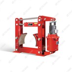
YW-E200/E30A Two-step Series Electro-hydraulic Drum Brakes
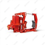
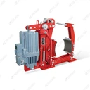
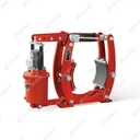
The YW-E200/E30A two-step series electro-hydraulic drum brake is a specialized dual-stage braking device designed for medium-load industrial equipment. It exclusively pairs with the ED30/5 electro-hydraulic thruster (rated thrust matching the E30 series), complies with installation standards...
Description
The YW-E200/E30A two-step series electro-hydraulic drum brake is a specialized dual-stage braking device designed for medium-load industrial equipment. It exclusively pairs with the ED30/5 electro-hydraulic thruster (rated thrust matching the E30 series), complies with installation standards DIN15435 and JB/T7021-2006, and features a unique two-step braking mechanism. This design ensures smooth deceleration and reliable holding, making it ideal for non-explosive environments like crane travel mechanisms and belt conveyors that require stable, impact-free braking.
Core Technical Specifications
| Parameter | Standard Value | Notes |
|---|---|---|
| Rated Drum Diameter | 200 mm | Matches medium-load equipment drum dimensions |
| Braking Torque (Two-Step) | - Step 1 (Deceleration): 80–160 N·m- Step 2 (Holding): 80–155 N·m- Total Torque: 315 N·m | Step 1 torque adjustable for smooth deceleration; Step 2 enhances holding safety |
| Matching Thruster Model | ED30/5 | 3-phase AC 380V/50Hz, electro-hydraulic drive |
| Brake Shoe Clearance | 0.8–1.2 mm | Ensures no friction during release |
| Step 2 Braking Time | 1–15 seconds | Adjustable via one-way speed control valve in the damping cylinder circuit |
| Friction Lining Material | Non-asbestos wear-resistant composite | Friction coefficient ≥0.38; low heat fading |
| Protection Class | IP54 | Dustproof and water-resistant, adaptable to outdoor/indoor workshops |
| Working Conditions | - Ambient Temperature: -20℃~+50℃- Relative Humidity: ≤90%- Altitude: ≤1000m (per GB755-2000) | No flammable, explosive, or corrosive gases |
| Key Installation Dimensions (mm) | A=500, E=190, H=520, h1=160 | Standardized per DIN15435 for universal mounting |
| Weight (w/o Thruster) | ~46 kg | Compact structure for space-constrained installations |
Core Structural & Functional Feature: Two-Step Braking Mechanism
The most distinctive advantage of the YW-E200/E30A is its two-step braking design, which solves the problem of equipment impact caused by one-time heavy braking and ensures reliable holding after stopping-consistent with the functional logic of YW-E series brakes in Summaries 1, 2, and 3:
Step 1: Smooth Deceleration BrakingWhen the equipment needs to stop, the control system first triggers the first-stage braking. The ED30/5 thruster reduces hydraulic pressure moderately, allowing the brake's primary spring to apply a smaller, adjustable torque (80–160 N·m) to the brake shoes. This slows the rotating drum gradually, avoiding sudden speed drops that could damage the equipment or cause material displacement (critical for belt conveyors and crane travel mechanisms).
Step 2: Reliable Holding BrakingAfter the equipment comes to a complete stop (detected by the control system or limit switch), the second-stage braking activates. The thruster further reduces pressure, and the brake's secondary spring (or damping cylinder) adds additional torque (80–155 N·m). At the same time, the one-way speed control valve adjusts the braking time (1–15 seconds) to ensure the brake shoes clamp the drum tightly without rebound. This prevents the equipment from sliding (e.g., cranes in windy conditions) or reversing (e.g., belt conveyors with inclined sections).
Damping Cylinder for Adjustable TimingThe built-in damping cylinder in the hydraulic circuit controls the transition between Step 1 and Step 2. By rotating the one-way speed control valve, operators can adjust the second-stage braking time according to actual needs-shorter times for fast-response scenarios (e.g., crane emergency stops) and longer times for fragile material transport (e.g., glass or precision parts conveyors).
Working Principle (Integrated Two-Step Logic)
The brake operates in the "electro-hydraulic release + two-step spring braking" mode, relying on the ED30/5 thruster and dual-stage mechanical components:
Power-On Release (Equipment Operation)When the host equipment starts, the ED30/5 thruster is energized. Its motor drives the centrifugal pump to pressurize hydraulic oil, pushing the push rod to extend. The push rod acts on the brake's lever mechanism, overcoming the pre-tightening force of both primary and secondary springs. This separates the brake shoes from the 200 mm-diameter drum (clearance 0.8–1.2 mm), and the brake is fully released for normal equipment operation.
Power-Off Two-Step Braking (Equipment Stop)
Step 1 Trigger: When the equipment stops, the thruster's power is reduced (not fully cut off), lowering hydraulic pressure. The primary spring rebounds first, driving the brake arms to swing inward and applying the first-stage torque (80–160 N·m) to slow the drum.
Step 2 Trigger: Once the drum stops, the control system cuts off additional thruster power. The secondary spring (or damping cylinder) activates, adding the second-stage torque (80–155 N·m). The adjustable speed control valve ensures the brake shoes clamp the drum gradually, achieving stable holding.
Release Reset: When the equipment restarts, the thruster re-pressurizes, pushing the push rod to overcome both springs' force and separating the shoes from the drum-returning to the release state.
Typical Applications (Aligned with YW-E Series Scenarios)
Based on Summaries 1, 2, and 3, the YW-E200/E30A is specifically optimized for scenarios requiring smooth deceleration and reliable holding:
Crane Travel Mechanisms
Large/medium outdoor cranes (bridge cranes, gantry cranes) for their 大车运行机构 (long travel) and 小车运行机构 (cross travel). The two-step braking prevents the crane from "shaking" during stops and resists wind loads to avoid sliding (ideal for open-air ports or construction sites).
Special cranes (e.g., container handling cranes) that require precise positioning-Step 1's smooth deceleration ensures containers are placed accurately, while Step 2's holding torque prevents shifting.
Belt Conveyors
Inclined or horizontal belt conveyors for bulk material transport (coal, cement, grain). Step 1 braking avoids material "piling" at the front of the belt, and Step 2 braking prevents the belt from reversing (critical for inclined conveyors to avoid material falling and equipment damage).
Conveyors for fragile materials (e.g., ceramic tiles, electronic components)-adjustable Step 2 timing ensures gentle clamping, protecting both the conveyor and materials.
Other Medium-Load Equipment
Small winches or hoists for light lifting (e.g., workshop parts handling). The two-step braking ensures loads are lowered smoothly and held securely when suspended.
Auxiliary drive shafts for metallurgical equipment (e.g., small rolling mill feed mechanisms)-stable braking prevents material jams during production.
Installation & Maintenance Guidelines
Installation Key Points
Standard Alignment: Follow DIN15435 and JB/T7021-2006 to align the brake's mounting holes with the equipment interface (e.g., A=500 mm, E=190 mm). Use a level to ensure the base is horizontal (error ≤0.5 mm/m) to avoid uneven lining wear.
Thruster Matching: Mount the ED30/5 thruster vertically, ensuring its push rod is coaxial with the brake lever's force application point (no lateral force) to maintain stable two-step torque output.
Timing Adjustment: After installation, test the Step 2 braking time using the speed control valve-adjust to 3–5 seconds for general use (or as per equipment requirements) and verify smooth transition between steps.
Maintenance Schedule
| Cycle | Tasks | Details |
|---|---|---|
| Daily | Visual Inspection | Check lining wear (replace if thickness ≤3 mm), drum surface (no oil stains/scratches), and thruster oil level (between MAX/MIN). |
| Monthly | Two-Step Function Test | Activate braking to confirm Step 1 deceleration is smooth and Step 2 holding is secure; re-adjust the speed control valve if timing is abnormal. |
| Quarterly | Thruster & Damping Cylinder Maintenance | Replace the ED30/5 thruster's hydraulic oil (ISO VG46); clean the damping cylinder's speed control valve to prevent clogging. |
| Annually | Torque & Spring Check | Test Step 1/Step 2 torques (ensure they fall within 80–160 N·m and 80–155 N·m); replace springs if elasticity decreases (signs: torque drop >15%). |
Common Faults & Solutions
| Fault Phenomenon | Possible Causes | Solutions |
|---|---|---|
| No Step 2 braking | Damping cylinder clogging; speed control valve stuck | Disassemble and clean the damping cylinder; replace the speed control valve if stuck. |
| Abnormal Step 2 timing | Valve adjustment error; hydraulic oil viscosity too high | Re-adjust the speed control valve; replace with ISO VG46 oil if viscosity is abnormal. |
| Insufficient Step 1 torque | Primary spring fatigue; thruster pressure too high | Replace the primary spring; reduce thruster hydraulic pressure (via relief valve). |
| Lining uneven wear | Brake base misalignment; drum runout excessive | Realign the base to horizontal; re-machine the drum if runout >0.1 mm. |
Hot Tags: yw-e200/e30a two-step series electro-hydraulic drum brakes, China, manufacturers, supplier, factory, customized, Electro hydraulic drum brakes TYPE YW K, Electro Hydraulic Thruster Operated Drum Brakes, Electro Thrust Industrial Brakes, inserted type crane drum brake, Series YW K acc to DIN 15 435, YW K series electro hydraulic drum brakes
You Might Also Like