Latest Products


Contact Us
- Wei Four Road, Weizhuang industrial Park, Changyuan District, Xinxiang City, Henan Province, China
- sales@zybc.com
- +86-373-7136666


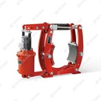
YWZ9-300/E50A Series Electro-hydraulic Drum Brakes
Working Principle of YWZ9-300/E50A Series Electro-Hydraulic Drum Brakes The YWZ9-300/E50A series adopts the core working mode of "electro-hydraulic release + spring braking" , which is consistent with the functional logic of YWZ9 series brakes (Summaries 1, 3, 5). It relies on the...
Description
Working Principle of YWZ9-300/E50A Series Electro-Hydraulic Drum Brakes
The YWZ9-300/E50A series adopts the core working mode of "electro-hydraulic release + spring braking", which is consistent with the functional logic of YWZ9 series brakes (Summaries 1, 3, 5). It relies on the coordinated operation of the matched E50A electro-hydraulic thruster and internal mechanical components to realize two key states: brake release (equipment operation) and brake application (equipment stop/emergency), with built-in auxiliary adaptive mechanisms to ensure stable performance.
1. Brake Release (Power-On State for Equipment Operation)
When the host equipment (such as cranes, conveyors) needs to start, the control system supplies 3-phase AC 380V power to the E50A thruster, and the release process follows three steps of energy conversion and force transmission:
Electro-Hydraulic Energy Conversion: The thruster's motor drives the internal centrifugal pump to rotate, drawing hydraulic oil from the thruster's oil tank and pressurizing it (consistent with the hydraulic pressure-building principle in Summary 2). The high-pressure oil pushes the thruster's piston and push rod to extend linearly.
Mechanical Force Transmission: The extended push rod acts on the brake's lever mechanism. Through the lever's force-amplifying effect, it overcomes the pre-tightening force of the brake's main compression spring (Summary 5), driving the two symmetric brake arms to swing outward.
Brake Release Execution: The outward-swinging brake arms drive the brake shoes (with non-asbestos friction linings) to separate from the 300 mm-diameter brake drum. The gap between the lining and the drum is maintained at the standard 1.0 mm (as per the brake's technical parameters), ensuring no friction between the lining and the drum during equipment operation. At this point, the brake is fully released, and the host equipment can run normally.
2. Brake Application (Power-Off State for Equipment Stop/Emergency)
When the equipment needs to stop normally or encounters a power failure, the E50A thruster loses power, and the system switches to spring-driven braking to achieve fail-safe protection (the core advantage emphasized in Summaries 1, 3, 5):
Hydraulic Pressure Disappearance: The thruster's motor stops running, the centrifugal pump ceases to build pressure, and the hydraulic pressure in the oil circuit dissipates rapidly. The thruster's push rod retracts under the reset force of its internal small spring (Summary 2).
Spring Force Driven Braking: As the push rod retracts, the constraint on the brake's lever mechanism is removed. The pre-compressed main spring rebounds instantly, generating a large clamping force and pulling the two brake arms to swing inward (Summary 1).
Friction Braking Implementation: The inward-swinging brake arms press the friction linings tightly against the outer surface of the rotating brake drum. According to the friction braking principle (Summary 5), the contact between the lining and the drum generates tangential friction force, converting the equipment's kinetic energy into heat energy (which is dissipated into the air). This friction force forms a braking torque of 400–630 N·m (the brake's rated torque range), forcing the brake drum and the connected equipment drive shaft to stop rotating quickly. The entire braking response time is ≤0.6 seconds, meeting emergency safety requirements.
3. Auxiliary Adaptive Adjustment Mechanism
To maintain stable braking performance during long-term use, the YWZ9-300/E50A is equipped with two key adaptive functions, which are consistent with the design of YWZ series brakes described in Summaries 1 and 3:
Automatic Lining Wear Compensation: During repeated braking, the friction lining will gradually wear, leading to an increase in the lining-drum gap. At this time, the built-in mechanical compensation device (optional, as per user needs) will trigger: when the brake arms swing inward during braking, the compensation device's ratchet and pawl mechanism engage, automatically extending the length of the brake shoe connecting rod. This resets the lining-drum gap to the standard 1.0 mm, avoiding reduced braking torque due to excessive gaps and eliminating the need for frequent manual adjustment.
Manual Release Backup: For scenarios where the thruster fails and the brake cannot be released electrically, the brake can be equipped with a manual release device (optional). By rotating the manual release handle, the lever mechanism is forced to overcome the main spring force, separating the lining from the drum-ensuring equipment maintenance or emergency movement (Summary 1).
Core Advantage of the Working Principle: Fail-Safe Design
The most critical feature of this working principle is its fail-safe nature (Summaries 1, 3, 5). In any abnormal situation (power failure, thruster malfunction, control system failure), the brake does not rely on external electrical or hydraulic energy. Instead, it automatically clamps the drum using the mechanical force of the main spring to achieve braking, fundamentally preventing equipment slipping, runaway, or other safety accidents. This is particularly important for medium-load equipment such as cranes and conveyors that require high operational safety.
Hot Tags: ywz9-300/e50a series electro-hydraulic drum brakes, China, manufacturers, supplier, factory, customized, Port machinery Disc brake, crane drum brakes with m function, Drum Brake Type YW K, normally open electro hydraulic drum brakes, durable crane drum brake, Electro Hydraulically Drum Brakes
You Might Also Like