1. Installation Methods
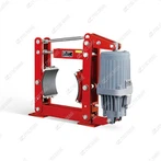
BYT1 series flameproof electro-hydraulic thrusters are special drive units for explosion hazardous environments, compliant with GB3836.1 / GB3836.2 flameproof standards (mark: Exd I for underground coal mines, Exd IIB T4 for chemical flammable gas sites). Vertical upward mounting (push rod facing up) is standard; inclined installation within ±15° is permitted, horizontal upside-down mounting is strictly forbidden for standard models.
Standard Vertical Installation
Verify model, rated thrust and explosion-proof certificate match site requirements before assembly; wipe dust, rust and oil on the flameproof housing surface, check push rod free lifting without jamming.
Fasten the bottom mounting lug firmly to the brake swing arm bracket with high-strength anti-loose bolts; ensure the entire thruster can swing freely during operation, push rod must not bear radial side load.
Connect the adjustable push rod assembly to the brake arm via hinge pin + cotter pin, reserve sufficient stroke margin to avoid over-travel jacking or insufficient brake opening clearance.
Fill dedicated anti-wear hydraulic oil from the oil filling plug to the oil level observation hole; repeatedly pull the push rod up and down to exhaust internal air, then tighten all oil plugs completely.
Flameproof wiring operation: Open the junction box with special spanner only when power is fully cut off. Select explosion-proof cables matching the rubber sealing grommet size to eliminate gaps, connect three-phase power and grounding wire reliably, fasten all flameproof joint bolts evenly to guarantee explosion isolation performance.
Reserve surrounding space for oil filling, seal replacement and regular flameproof gap inspection; avoid long-term splashing water and corrosive gas erosion of the flameproof enclosure.
Allowed Inclined Installation (≤±15° tilt angle only)
Keep push rod facing upward at all times; adjust mounting bracket angle to control tilt within 15°, larger tilt will cause oil starvation, air trapping and slow response.
Recheck liquid level after tilting assembly, supplement hydraulic oil to standard scale; reinforce pipeline joints to prevent vibration loosening.
Custom modified horizontal BYT1 variants are required if horizontal layout is mandatory; standard vertical BYT1 cannot be laid horizontally directly.
Critical Explosion-Proof Installation Mandatory Requirements
Strictly forbid replacing original flameproof housing, cable grommets, bolts and sealing parts with non-certified ordinary spare parts; damaged flameproof surfaces must be repaired before use.
Reliable grounding via reserved grounding screw on the thruster body; ungrounded installation is prohibited in explosive areas.
Never open the wiring cover while energized; regular inspection of flameproof joint clearance per mine/chemical safety specifications.
Power supply options: 3-phase AC 127V / 220V / 380V / 660V / 1140V, matched with site explosion-proof power distribution system.
Ambient limits: Altitude ≤1000m, ambient temperature -20℃ ~ +40℃, monthly average humidity ≤90% without persistent condensation.
2. Standard Matching Accessories
Core Functional Flameproof Supporting Components
Adjustable Flameproof Connecting Push Rod AssemblyConsists of threaded stroke-adjustable rod, hinge pins, cotter pins and wear-resistant joint sleeves for linkage between thruster and brake arm; all fasteners are anti-spark certified for hazardous zones.
Original Flameproof Junction Box & Cable Sealing GlandIntegrated flameproof terminal base, matched rubber cable sealing rings to block flammable gas penetration; special opening spanner is supplied as standard for wiring maintenance.
Stroke Lock Adjustment NutsLock the effective extension length of push rod to fix brake opening stroke, prevent loosening under frequent vibration.
Flameproof Grounding AssemblySpecial anti-rust grounding bolt and copper braided ground wire for mandatory equipotential connection.
Consumable Maintenance Spare Parts
Full Hydraulic Sealing Repair KitIncluding piston oil seals, dust-proof rod rings, end cover flameproof gaskets and O-rings to eliminate hydraulic leakage without breaking flameproof integrity.
Special Low-Temperature Anti-Wear Hydraulic OilModel-specific hydraulic fluid (VG32/VG46/transformer oil for low-temperature sites) for periodic oil replacement; oil grade selected per ambient temperature.
Flameproof Motor Replacement SparesCertified flameproof stator coils, centrifugal pump impellers and rolling bearings for motor burnout or pump jamming repair; non-flameproof motor parts are not interchangeable.
Liquid Level Sight Glass AssemblyExplosion-proof sealed oil window for real-time internal oil volume observation.
3. Optional Custom Explosion-Proof Accessories
Explosion-Proof Stroke Limit Switches (E1/E2/EB types)E1: upper travel switch; E2: lower travel switch; EB: inductive non-contact flameproof switch, feedback brake fully-open/fully-closed signals to explosion-proof PLC control system.
Extended Custom Push RodsLong-stroke connecting rods for large-torque flameproof drum/disc brakes with long travel demand.
Integrated Rain & Dust Flameproof Outer Protective CoverFor open-air coal stockyards, port explosion-proof crane outdoor operation, isolate dust, rain and salt fog from flameproof housing.
Buffer Limit SleevesReduce mechanical impact when push rod reaches full extension/retraction stroke, lower vibration risk in explosive environments.
Anti-Corrosion Coated Flameproof Housing & Stainless Steel FastenersFor coastal chemical plants and salt-fog corrosive hazardous zones, avoid rust damage to flameproof joint surfaces.
Explosion-proof Oil Drain & Fitting Auxiliary ValvesConvenient oil change without dismounting the entire thruster in confined underground mine spaces.