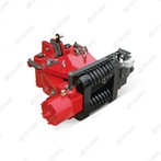
The DYTZW700-S/110 electro-hydraulic pusher is an integrated linear actuator combining motor, hydraulic pump, cylinder, and control valve block, designed for industrial applications requiring medium thrust and precise positioning. It is commonly used in gate control, material handling, and brake systems in metallurgy, power, and water conservancy sectors. Below is a detailed breakdown of its specifications, structure, operation, maintenance, and troubleshooting.
Core Technical Specifications
| Parameter | Value | Notes |
|---|---|---|
| Rated Thrust | 7000 N (700 kgf) | Standard for DYTZW700 |
| Rated Pull Force | 5100 N (510 kgf) | Typical for this series |
| Rated Speed (Push/Pull) | 110 mm/s / 140 mm/s | Push speed specified as 110 mm/s |
| Stroke (S) | Customizable (50–1500 mm) | "S" denotes stroke length |
| Motor | Y90S-4, 1.1 kW, 3-phase AC 380V/50Hz | IP54 protection |
| Hydraulic Oil | ISO VG46 anti-wear hydraulic oil | Operating temp: -25℃ to +50℃ |
| Protection Features | Hydraulic lock (self-locking), overload protection | Safety during power failure |
| Mounting | Flange/foot/clevis | Versatile installation options |
Structural Features
Integrated Design
No external hydraulic pipes; all components (motor, pump, cylinder, valve block) are housed in a sealed steel casing, reducing leakage and contamination risks.
Equipped with a transparent oil level gauge and drain plug for easy maintenance.
Hydraulic Lock (Self-Locking)
Built-in hydraulic lock (check valve) holds the push rod in position when powered off, preventing accidental movement and enhancing safety.
Control Valve Block
Includes overflow valve (overload protection), speed control valve (adjustable push/pull speed), and check valves for stable operation.
Sealing System
High-performance oil seals (nitrile rubber or FKM) on the piston rod and cylinder to minimize leakage and extend service life.
Working Principle
Extension (Push)
Motor drives the hydraulic pump to generate pressure oil, which flows through the control valve block into the cylinder's rodless chamber.
Hydraulic pressure pushes the piston and rod outward, achieving the pushing action. The hydraulic lock ensures position retention if power is cut.
Retraction (Pull)
Reverse motor rotation reverses oil flow, directing pressure to the rod chamber.
The piston and rod retract under hydraulic force, with the return spring aiding reset (where applicable).
Self-Locking
The hydraulic lock engages automatically when the motor stops, locking the rod in place to prevent drifting.
Maintenance Guidelines
1. Daily Inspection (5–10 minutes/shift)
Oil Level & Quality: Ensure oil is between MAX/MIN marks; check for discoloration or contamination (replace if cloudy).
Leakage: Inspect rod, end cover, and drain plug for oil drips.
Mechanical Movement: Manually test rod movement for smooth operation (no jamming).
Electrical Check: Inspect motor cables/terminals for wear; verify grounding and listen for abnormal noise during operation.
2. Periodic Maintenance
| Interval | Tasks | Details |
|---|---|---|
| 1 Month | Lubrication & Fasteners | Apply lithium-based grease to rod and joints; tighten mounting bolts (torque: 25–30 N·m). |
| 3 Months | Oil Change & Bleeding | Drain old oil, flush with clean ISO VG46 oil, refill to MAX; bleed air by cycling power 3–5 times. |
| 6 Months | Valve Block & Filter | Clean or replace the oil filter; inspect valve block for leaks or blockages. |
| 12 Months | Overhaul | Replace seals, check piston/cylinder for wear, test hydraulic lock functionality, and calibrate thrust. |
3. Special Environment Maintenance
High Dust: Install a dust cover; shorten oil change intervals to 2 months.
Low Temperature: Use ISO VG32 low-temp oil; preheat for 5–10 minutes before operation.
Coastal/Salt-Fog: Apply anti-rust coating monthly; use stainless steel fasteners.
Common Faults & Solutions
| Fault | Possible Causes | Solutions |
|---|---|---|
| Rod fails to extend | Low oil level, motor burnout, pump blockage | Refill oil; test motor insulation (≥1 MΩ); clean/replace pump impeller. |
| Insufficient thrust | Air in system, oil contamination, worn piston seals | Bleed air; replace oil; inspect and replace seals. |
| Rod drifts (no self-locking) | Hydraulic lock failure, valve block leakage | Check/replace hydraulic lock; repair valve block. |
| Motor overheating | Exceeded duty cycle, blocked ventilation | Reduce cycle frequency; clean motor vents. |
Safety Precautions
Lockout-Tagout: Cut power and hang warning signs before maintenance to prevent accidental startup.
Oil Compatibility: Use only recommended ISO VG46 oil; avoid mixing brands/types.
Avoid Overload: Do not exceed rated thrust (7000 N) to prevent damage to the pump or cylinder.
Grounding: Ensure reliable motor grounding to prevent electric shock.