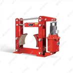
The QW Series is a range of industrial-grade pneumatic drum brakes engineered for reliable braking control in light, medium, and heavy-duty rotating machinery-including cranes (overhead, gantry), winches, conveyors, mining equipment, and material-handling systems. Defined by its pneumatic actuation (compressed air drives braking force) and drum-style friction structure, this series delivers dynamic deceleration, static load holding, and fail-safe emergency stopping. It is particularly suited for environments where compressed air is readily available (e.g., factories, ports, mining sites) and offers advantages like fast response, low maintenance, and resistance to harsh conditions. Covering drum diameters from 150–800mm and torque outputs from 80–6,000 N·m, the QW Series meets the needs of industries prioritizing cost-efficiency and consistent performance. Below is a detailed breakdown of its series characteristics, core structure, working principle, key features, typical applications, and technical specifications:
1. Series Overview & Core Function
The QW Series follows the "QW" naming convention (Q = Pneumatic actuation, W = Drum-style braking) and is designed to address diverse industrial braking needs. Its core functions align with safety and operational requirements:
Dynamic Braking: Decelerating or stopping rotating machinery (e.g., conveyor belts, crane hoists) with controlled torque to avoid load sway, mechanical shock, or component damage.
Static Load Holding: Securing loads in place during downtime, maintenance, or process pauses (e.g., suspending a crane load mid-air).
Emergency Braking: Automatically engaging in air pressure loss or system faults to prevent equipment runaway-critical for high-risk operations like mining hoists or port winches.
The series includes sub-models tailored to duty cycles: light-duty (0.5–10 tons), medium-duty (10–50 tons), and heavy-duty (50–200 tons), ensuring compatibility with a wide range of machinery.
2. Core Structure & Key Components
The QW Series features a modular, rugged design optimized for pneumatic actuation and drum braking, with four integrated subsystems:
2.1 1. Pneumatic Actuation Unit (Power Core)
The unit converts compressed air into mechanical force to drive brake engagement/release, comprising:
Air Cylinder: A sealed, high-strength steel or aluminum cylinder (rated for 0.4–0.8 MPa working pressure) with a precision-machined piston. It uses nitrile rubber (NBR) or fluoropolymer (FKM) seals to prevent air leakage, even in extreme temperatures (-30°C to 120°C).
Air Control Valve: An integrated 2/2 or 3/2 solenoid valve (or manual valve for basic models) that regulates air intake and exhaust. It enables fast pressure buildup (≤ 0.3 seconds) for quick brake release and controlled pressure reduction for smooth engagement.
Air Filter & Regulator (Optional): A combination filter-regulator-lubricator (FRL) unit that cleans compressed air, adjusts pressure to match braking needs, and lubricates internal components-extending the cylinder's service life.
2.2 2. Drum Braking Assembly (Friction Core)
The assembly interfaces with the machinery's rotating drum to generate braking force, including:
Brake Shoes: Single or double arcuate shoes made of ductile iron (QT400/QT500) for impact resistance. Light/medium-duty models use lightweight aluminum alloy shoes to reduce inertia.
Friction Linings: Application-specific materials tailored to duty cycles:
Light-duty: Resin-based composites (μ ≥ 0.38, heat resistance up to 280°C) for low-wear, low-noise operation.
Medium/Heavy-duty: Semi-metallic composites (μ ≥ 0.42, heat resistance up to 350°C) for high-torque, high-frequency braking.Linings are bolted or bonded to shoes for easy replacement, with wear indicators (mechanical tabs) to signal maintenance.
Drum Compatibility: Designed for standard industrial drums (diameter: 150–800mm, thickness: 10–30mm, material: 45# steel or cast iron). Adjustable shoe brackets accommodate ±3mm drum alignment variations, simplifying installation.
2.3 3. Fail-Safe Spring Mechanism (Safety Core)
A mandatory feature for all QW Series models, this mechanism ensures braking capability in air pressure loss scenarios:
High-Tension Compression Springs: 1–4 manganese-steel springs (calibrated to 2–30 kN force, based on torque) housed in the brake base. When compressed air is supplied (brake release), the springs compress; if air pressure drops (e.g., compressor failure), the springs expand instantly-pushing the brake shoes against the drum to lock the shaft.
Spring Redundancy (Heavy-Duty Models): Dual spring sets for critical applications (e.g., mining hoists), ensuring emergency braking even if one spring fails.
2.4 4. Adjustment & Protection Components (Durability Core)
Brake Gap Adjusters: Threaded rods or eccentric pins that allow operators to fine-tune the gap between shoes and drum (optimal: 0.3–0.6mm) to compensate for lining wear. Some medium/heavy-duty models include automatic gap adjusters for minimal maintenance.
Environmental Protection:
Light/medium-duty: Epoxy resin coating (thickness ≥ 60μm) for dust and moisture resistance (IP64).
Heavy-duty: Hot-dip galvanizing + epoxy coating (IP65) for corrosion resistance in saltwater (ports) or mining dust.
Vibration Resistance: Anti-loosening fasteners (lock nuts, spring washers) secure components to withstand machinery vibration (e.g., conveyor belts, crane travel), preventing performance degradation.
3. Working Principle
The QW Series operates on a pneumatic fail-safe cycle, adapting to industrial machinery operation:
3.1 1. Brake Release (Normal Operation)
When the machinery (e.g., a factory overhead crane) is activated, the control system sends a signal to the pneumatic valve.
Compressed air (0.4–0.8 MPa) is supplied to the air cylinder, pushing the piston and actuating a lever mechanism. This force overcomes the tension of the fail-safe springs.
The lever pulls the brake shoes away from the drum, creating a small gap. The drum (connected to the machinery's shaft) rotates freely, enabling lifting, conveying, or winching.
3.2 2. Brake Engagement (Controlled Stopping/Holding)
Controlled Stopping: To slow or stop the machinery, the pneumatic valve exhausts air from the cylinder. Air pressure drops, and the fail-safe springs begin to expand-pushing the brake shoes against the rotating drum.
Torque Generation: Friction between linings and drum generates braking torque (80–6,000 N·m), decelerating the drum at a controlled rate (0.5–1.5 seconds, depending on model) to avoid load instability.
Static Holding: For mid-cycle pauses (e.g., holding a load at a workstation), the cylinder retains low air pressure (~0.1–0.2 MPa). Reduced pressure allows the springs to partially engage the brake, holding the load securely without straining components.
3.3 3. Emergency Braking (Air Pressure Loss)
In case of air pressure loss (e.g., compressor failure, air line leak), the cylinder loses all force to counteract the springs.
The springs fully expand within milliseconds (0.4–0.8 seconds), slamming the brake shoes against the drum to lock the shaft. The brake stops the machinery instantly, preventing load drops, collisions, or equipment runaway.
4. Key Features of the QW Series
The QW Series stands out for its pneumatic-specific advantages and industrial adaptability:
4.1 1. Fast Response & High Efficiency
Pneumatic actuation enables rapid brake release/engagement (≤ 0.3 seconds for release, ≤ 0.5 seconds for emergency engagement)-critical for machinery with short cycle times (e.g., packaging conveyors, small cranes).
4.2 2. Low Maintenance & Cost-Effective
No hydraulic fluid (eliminates leakage risks, fluid replacement, and contamination issues common in hydraulic brakes).
Friction linings are easy to replace (≤ 20 minutes for light-duty models), and air cylinders require minimal service (annual lubrication only).
Compressed air is often readily available in industrial settings, reducing the need for additional power sources (e.g., hydraulic pumps).
4.3 3. Environmental Resilience
Resistant to temperature extremes (-30°C to 120°C) and harsh conditions (dust, moisture, mild chemicals), making it suitable for indoor (factories) and outdoor (ports, construction) applications.
No fluid spills, complying with environmental regulations (e.g., ISO 14001) for clean manufacturing.
4.4 4. Versatile & Scalable
Covers a wide torque range (80–6,000 N·m) and drum diameter (150–800mm), adapting to light-duty tools (mini winches) and heavy-duty equipment (mining hoists). Sub-models offer customizable options (e.g., automatic adjusters, FRL units) for specific needs.
4.5 5. Safety Compliance
Meets global industrial safety standards, including ISO 4301-1 (crane brakes), GB/T 6333-2019 (Chinese pneumatic drum brake standards), and CE (EU Machinery Directive). Heavy-duty models comply with mining safety regulations (e.g., ATEX for explosive environments).
5. Typical Applications
The QW Series is widely used across industries where compressed air is accessible, with key applications by duty cycle:
| Duty Cycle | Applications |
|---|---|
| Light-Duty | Small jib cranes (workshops), mini winches (automotive repair), packaging conveyors, textile machine drives, small mixers. |
| Medium-Duty | Overhead cranes (factories), gantry cranes (warehouses), shipyard winches (small cargo), cement plant conveyors, food processing machinery. |
| Heavy-Duty | Mining hoists (ore lifting), port container cranes, steel mill rolling mills, construction cranes, heavy-duty conveyors (coal, ore). |