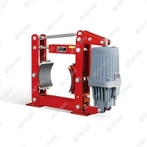
The installation of the TYW-315 foot-operated hydraulic drum brake requires strict adherence to steps such as pre-installation preparation, mechanical fixing, hydraulic/electrical connection, and post-installation debugging to ensure stable braking performance. Below are the specific and actionable installation steps:
1. Pre-Installation Preparation
1.1 Component & Parameter Verification
Confirm the brake model (TYW-315) matches the equipment (small/medium gantry cranes, tower cranes) and that the brake drum diameter (315 mm) aligns with the equipment's rotating mechanism.
Inspect all components for damage: check the brake body, foot hydraulic pump, high-pressure oil pipes, seals, manual brake lever, and mounting bolts for cracks, deformation, or aging (replace damaged parts immediately).
Verify the hydraulic oil type: use DB-25 hydraulic oil for -20℃ to 50℃; switch to YH-10 aviation hydraulic oil for temperatures below -20℃.
1.2 Installation Environment & Tool Preparation
Ensure the installation position (crane rotating mechanism) is dry, clean, and free of oil stains/rust. Reserve ≥15 cm of space around the brake for maintenance and heat dissipation.
Prepare tools: torque wrench (0–500 N·m), feeler gauge (0.01–1 mm), cleaning cloth, sealant (hydraulic system-specific), adjustable wrench, and a funnel for oil injection.
1.3 Surface Cleaning
Thoroughly clean the brake's mounting surface (on the crane) and the brake drum's friction surface with a dry cloth. Remove rust, metal debris, or oil stains-impurities can cause unstable installation or reduced braking friction.
Polish minor rust on the brake drum surface with fine sandpaper (ensure no deep grooves or cracks; replace the drum if damaged).
2. Mechanical Installation (Core Step)
2.1 Fix the Brake Body
Lift the TYW-315 brake (net weight ≈42 kg) and align its mounting holes with the reserved holes on the crane's rotating mechanism. Ensure the brake is installed horizontally (use a level to check; deviation ≤±1° to avoid uneven braking force).
Fasten with 8.8-grade high-strength bolts (M16/M20, depending on equipment reserved holes). Tighten in a diagonal sequence to the specified torque (220–250 N·m for M16, 350–400 N·m for M20) to ensure uniform clamping force.
After fixing, shake the brake body gently to confirm no looseness or tilting.
2.2 Install the Brake Drum
Mount the brake drum onto the equipment's rotating shaft, ensuring a tight fit with the flat key (no gaps or slipping). Check the drum's coaxiality: radial runout ≤±0.2 mm, end runout ≤±0.3 mm (use a dial indicator to verify; adjust or replace the drum if exceeding limits).
Ensure the brake drum's friction surface is centered with the brake shoes (no eccentricity) to lay the foundation for subsequent gap adjustment.
2.3 Assemble the Manual Brake Device
Install the manual brake lever on the brake body's reserved interface. Fasten the connecting pins and cotter pins to ensure the lever moves flexibly without jamming.
Test the manual brake: pull the lever to confirm it can smoothly drive the brake shoes to clamp the drum; release the lever to ensure it rebounds fully (no stuck positions).
3. Hydraulic System Connection
3.1 Connect Oil Pipes
Connect the high-pressure oil pipe (equipped with the brake) between the brake's hydraulic cylinder interface and the foot pump's oil outlet. Ensure the pipe is not twisted, kinked, or stretched tightly (reserve a small amount of slack to avoid damage during equipment operation).
Apply hydraulic system-specific sealant to the pipe joints (avoid excess sealant entering the oil circuit). Tighten the joints with an adjustable wrench to ensure no leakage (do not over-tighten to prevent thread damage).
3.2 Inject Hydraulic Oil
Open the oil filler cap on the foot pump. Use a funnel to inject the matched hydraulic oil until the level reaches the "MAX" mark on the sight glass (do not overfill to avoid overflow during pressure buildup).
Screw the oil filler cap tightly to prevent dust or moisture from entering the system.
3.3 Bleed Air from the Oil Circuit
Keep the brake in the released state (foot pump not pressed). Loosen the air release valve on the brake's hydraulic cylinder (1–2 turns).
Slowly step on the foot pump repeatedly (10–15 times) until oil flows out of the air release valve without bubbles. Tighten the valve immediately while holding the foot pump slightly pressed (to maintain system pressure).
Repeat the bleeding process 2–3 times to ensure all air is 排出 -residual air will cause weak braking or delayed response.
4. Post-Installation Adjustment & Testing
4.1 Adjust Brake Clearance
Use a feeler gauge to measure the gap between the brake shoes (both sides) and the drum. The standard clearance is 0.3–0.5 mm.
Adjust the clearance through the adjusting bolts on both sides of the brake: turn clockwise to reduce the gap, counterclockwise to increase it. Ensure the gaps on both sides are equal (difference ≤0.1 mm) to avoid uneven wear of the linings.
4.2 Functional Test (No-Load)
Foot Brake Test: Step on the foot pump gradually-confirm the brake engages smoothly with increasing pedal force, and the rotating drum stops stably without jitter or abnormal noise. Release the pedal: the brake should release immediately, and the drum rotates freely.
Manual Brake Test: Pull the manual brake lever-verify the drum is locked tightly; release the lever, and the brake returns to the released state.
Leakage Check: After 10 minutes of pressure retention (foot pump half-pressed), check all oil pipe joints and the hydraulic cylinder for leakage. Wipe the surface and recheck to confirm no oil seepage.
4.3 Load Test (On-Site Verification)
After no-load testing passes, conduct a load test with the crane's rated load (50% → 100% load step-by-step).
Verify that the brake can stop the loaded equipment smoothly within the specified distance (no sliding or delayed braking). Check the pedal force: it should be labor-saving (consistent with the 10:1 lever ratio) without excessive resistance.
5. Final Inspection & Documentation
Recheck all fasteners (mounting bolts, oil pipe joints) for tightness; retighten if loose.
Clean the brake surface and surrounding area to remove oil stains or debris.
Record installation details: model, installation date, hydraulic oil type, brake clearance data, and test results for future maintenance reference.