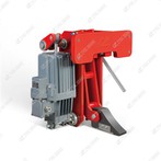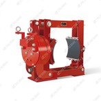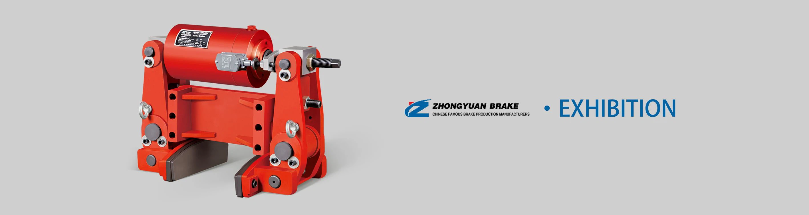
The YLZ Series is a range of industrial-grade hydraulic wheel brakes engineered for direct braking control on the wheels of heavy-duty mobile and fixed machinery, including port cranes, mining trucks, construction vehicles, gantry cranes, and material-handling equipment. Characterized by its direct wheel-mounted design and hydraulic actuation, this series delivers high braking force, stable performance, and reliable load holding-critical for applications requiring precise wheel speed control or emergency stopping (e.g., downhill mining trucks, port container handlers). With a focus on durability, impact resistance, and adaptability to harsh environments, the YLZ Series is widely used in ports, mines, construction sites, and logistics hubs. Below is a detailed breakdown of its core attributes, working principle, key features, typical applications, and technical specifications:
1. Series Overview & Core Function
The YLZ Series (Y = Hydraulic, L = Wheel-Mounted, Z = Heavy-Duty) is defined by its direct wheel integration, distinguishing it from shaft-mounted drum or disc brakes. Its core functions are tailored to wheeled machinery and heavy-load scenarios:
Dynamic Wheel Braking: Decelerating or stopping wheeled equipment (e.g., mining trucks, crane travel wheels) with controlled torque to avoid skidding, load sway, or mechanical shock.
Static Wheel Holding: Securing machinery in place during downtime, maintenance, or on inclines (e.g., parking mining trucks on slopes, locking crane wheels during load handling).
Emergency Anti-Skid Braking: Automatically engaging in system faults (e.g., hydraulic pressure loss, overspeed) to prevent wheel lock-up and equipment runaway-critical for high-risk operations like mine haulage.
Covering wheel diameters from 400–1,500mm and torque outputs from 5,000–50,000 N·m, the series caters to heavy-duty loads (50–500 tons) and large wheeled machinery.
2. Working Principle
The YLZ Series operates on a hydraulic clamping principle, where hydraulic pressure drives brake pads to clamp directly onto the wheel rim or a dedicated brake disc mounted on the wheel hub. Its working cycle includes three key states:
2.1 1. Brake Release (Normal Operation)
When the machinery (e.g., a port RTG crane) is in motion, the control system supplies hydraulic pressure (10–25 MPa) to the brake's hydraulic cylinders.
The pressurized cylinders retract, pulling the brake pads away from the wheel rim/disc and creating a gap (0.5–1.0mm). The wheel rotates freely, enabling normal travel or operation.
2.2 2. Brake Engagement (Controlled Stopping/Holding)
Controlled Stopping: To slow or stop the machinery, the control system reduces hydraulic pressure. Internal return springs (or reduced pressure) push the brake pads against the rotating wheel rim/disc.
Torque Generation: Friction between the pads and wheel interface generates braking torque, with force proportional to hydraulic pressure-allowing smooth, adjustable deceleration (e.g., mining trucks descending slopes).
Static Holding: For parking or load security, hydraulic pressure is fully released. Return springs (or a mechanical lock) keep the pads clamped to the wheel, maintaining torque to hold the machinery stationary without power consumption.
2.3 3. Emergency Braking (Fault Scenarios)
In case of hydraulic pressure loss, overspeed (detected by wheel speed sensors), or operator emergency input, the brake engages instantly.
Return springs (or backup hydraulic accumulators) drive the pads against the wheel with maximum force, generating peak torque to stop the wheel within ≤ 1.0 second (under rated load)-preventing skidding or runaway.