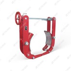
ED301/6Ex Series Explosion-Protected Electro-Hydraulic Thruster
The ED301/6Ex series explosion-proof electro-hydraulic thruster is a compact integrated drive device combining motor, centrifugal pump and oil cylinder, designed for driving explosion-proof brakes (e.g., DYW series drum brakes) in hazardous areas. It meets the explosion-proof requirements of GB3836.2-2000 and IEC standards, with explosion-proof markings Exd IIB T4 Gb/Ex tD A21 IP65 T130℃, suitable for IIA/IIB flammable gas zones and combustible dust zones (T1-T4 temperature classes), widely used in mining, petrochemical, and port industries.
Core Technical Specifications
| Parameter | Standard Value | Notes |
|---|---|---|
| Rated Thrust | 3000 N | Stable output under explosion-proof enclosure |
| Rated Stroke | 60 mm | External stroke limitation available |
| Motor Power | 550 W | 3-phase AC, insulation class F |
| Power Supply | 380V/660V/1140V, 50Hz/60Hz | Compatible with hazardous area power grids |
| Explosion-Proof Marking | Exd IIB T4 Gb/Ex tD A21 IP65 T130℃ | Dual protection for gas and dust environments |
| Working Temperature | -20℃ to +40℃ | Standard range; expandable with heating kit |
| Protection Class | IP65 | Dustproof and waterproof for harsh industrial conditions |
| Installation Angle | 0°–180° | Balance air chamber enables flexible mounting |
| Weight | ~45 kg | Compact design for easy integration with brakes |
Key Structural Features
Explosion-Proof Integrated Design
Flameproof enclosure with precision-machined flame paths to contain internal sparks; all electrical components (motor, terminals, limit switches) are explosion-proof certified.
Cable entry uses sealed explosion-proof joints, and the motor junction box is fully sealed to prevent gas/dust ingress, maintaining IP65 protection.
Electro-Hydraulic Drive Principle
When powered on, the motor drives the centrifugal pump to generate hydraulic pressure, pushing the piston rod to extend (release brake). When power is cut off, the return spring retracts the rod (applies brake), ensuring fail-safe operation.
Hydraulic operation ensures smooth, impact-free motion with high switching frequency (up to 2000 cycles/hour in S3 mode).
Durable & Low-Maintenance
Motor adopts non-immersed design with high insulation grade; all seals and bearings use international brand components for long service life.
Fasteners are stainless steel, and the cylinder surface is anti-corrosion coated, suitable for humid and corrosive environments.
Working Principle
Brake Release (Power-On): The motor drives the hydraulic pump to build pressure, pushing the piston rod to extend against spring force, separating brake shoes from the drum.
Brake Application (Power-Off): Hydraulic pressure drops, and the return spring pulls the rod back, clamping the brake shoes to the drum for emergency braking.
Interlock Protection: Equipped with explosion-proof limit switches to send release/closure signals to the control system, preventing equipment startup before full brake release.
Installation & Maintenance Guidelines
Installation Requirements
Mounting angle: 0°–180° (ensure balance air chamber is properly vented).
Use explosion-proof cables and certified connectors; tighten flame path bolts to specified torque (30–35 N·m).
Ensure proper alignment with the brake to avoid lateral forces on the piston rod.