
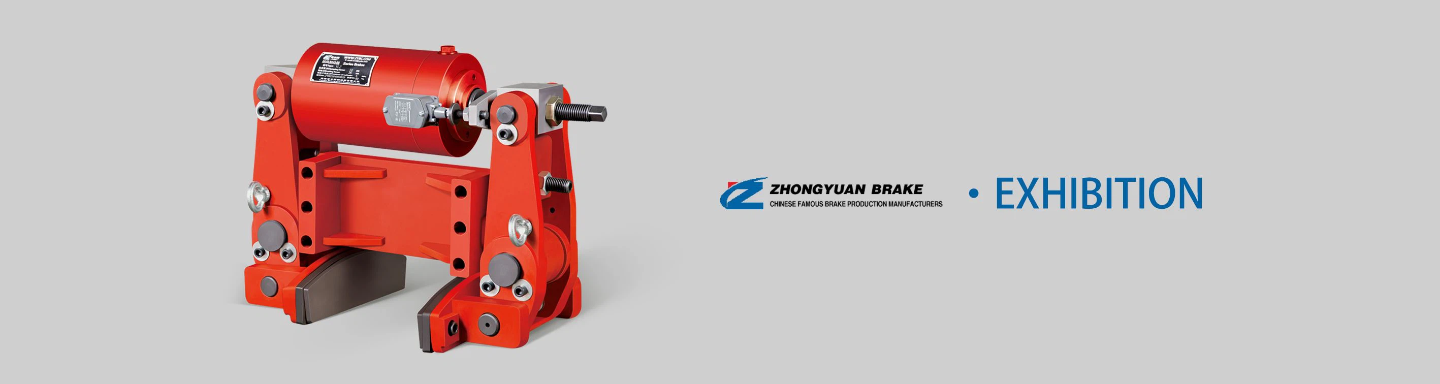
1. Model Interpretation & Core Function
The YWZ4(ZYTD)-150/D25's model code reflects its design optimization and matching components, facilitating quick equipment pairing:
| Model Segment | Meaning |
|---|---|
| YWZ4(ZYTD) | 4th-Generation Drum Brake with ZYTD-type structural optimization (spring-engaged, electro-hydraulic released) |
| 150 | Brake drum diameter: 150 mm (medium-sized drum for light-to-medium loads) |
| D25 | Matched electro-hydraulic thruster model (D-series, 25 denotes thrust/power parameters) |
Its core functions target safety and control for medium-duty machinery:
Normal Braking: Decelerating or stopping machinery smoothly during routine operation, adapting to intermittent or continuous working cycles.
Emergency Stopping: Rapidly engaging in power loss, overspeed, or system faults to prevent machinery runaway and potential accidents.
Static Load Holding: Securing loads (e.g., lifted goods, conveyor materials) during downtime, maintenance, or power outages to avoid accidental movement.
2. Working Principle
The YWZ4(ZYTD)-150/D25 operates on a fail-safe principle (spring-engaged for braking, electro-hydraulic thrust for release), ensuring safety even if the power or actuation system fails. Its working cycle includes three key states:
2.1 Brake Engagement (Safety State)
When the machinery is stationary, in emergency, or powered off, internal high-tension compression springs expand to push the dual brake shoes outward.
The brake shoes (lined with high-performance friction material) press tightly against the inner surface of the rotating drum. Friction between the shoes and drum generates stable braking torque, stopping the drum or holding it stationary.
2.2 Brake Release (Operating State)
When the machinery needs to run, the matched D25 electro-hydraulic thruster is activated. The thruster converts electrical energy into linear hydraulic thrust (rated: 250 N).
The thrust pulls the integrated lever mechanism, compressing the internal springs and retracting the brake shoes from the drum-creating a 0.3–0.6 mm clearance.
The drum rotates freely with the machinery shaft, enabling normal operation (e.g., conveyor movement, winch lifting).
2.3 Emergency Response (Fault State)
In case of power loss, thruster failure, or emergency shutdown, the thruster's thrust dissipates instantly.
The compression springs expand within ≤ 0.4 seconds, driving the brake shoes to clamp the drum-engaging the brake quickly to stop the machinery and avoid hazards.
3. Core Structure & Key Components
The YWZ4(ZYTD)-150/D25 features an optimized, modular design with four critical subsystems, balancing durability and ease of maintenance:
3.1 Brake Drum & Shoe Assembly (Friction Core)
Brake Drum: 150 mm diameter, made of HT250 gray cast iron with a quenched and tempered inner surface (hardness HB 200–240) for enhanced wear resistance and heat dissipation. It is mounted on the machinery shaft via a keyway and locking nut.
Brake Shoes: Two arc-shaped steel shoes (Q235 material) lined with ceramic-resin composite friction pads (friction coefficient μ ≥ 0.38). The pads are bolted to the shoes for quick replacement without disassembling the entire brake.
Shoe Support & Hinge: A cast steel support with wear-resistant bushings that ensures the shoes swing smoothly during engagement/release, avoiding jamming.
3.2 Actuation & Spring Mechanism (Power Core)
Matched D25 Electro-Hydraulic Thruster: Provides linear thrust (250 N) to release the brake. It integrates a three-phase AC motor (380V, 50Hz), hydraulic pump, and cylinder, with a rated power of 0.18 kW. The thruster features a compact design for easy integration.
Compression Springs: High-strength 65Mn steel springs that provide clamping force (3–4 kN) for brake engagement. The spring preload is adjustable via a nut to fine-tune braking torque.
Reinforced Lever Mechanism: Steel levers with thickened arms (5–8 mm) to transmit thrust efficiently, reducing deformation under load and ensuring consistent release performance.
3.3 Safety & Control Components (Control Core)
Limit Switches: Optional dual position sensors (one for "fully engaged," one for "fully released") that send signals to the machinery's PLC. This enables interlock control (machinery starts only when the brake is released, stops if the brake fails to engage).
Clearance Adjustment Screws: Located on the shoe support, they allow precise adjustment of the brake clearance (0.3–0.6 mm) to maintain stable braking performance as pads wear.
Manual Release Lever: A mechanical lever on the thruster for manual brake release during power loss, facilitating maintenance and emergency reset.
3.4 Mounting & Protection Components (Durability Core)
Adjustable Mounting Base: A steel base with slotted holes for ±8 mm horizontal/vertical adjustment, simplifying alignment with the brake drum during installation.
Dust & Splash Cover: A sheet metal cover with IP55 protection, shielding internal components from dust, light water splashes, and industrial debris.
Anti-Corrosion Coating: Epoxy resin coating (80–100 μm) on external metal parts to resist rust and mild chemical corrosion (e.g., industrial dust, humidity).


