Latest Products


Contact Us
- Wei Four Road, Weizhuang industrial Park, Changyuan District, Xinxiang City, Henan Province, China
- sales@zybc.com
- +86-373-7136666


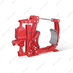
DYW315-900 Series Explosion Protected Electro-hydraulic Drum Brakes
DYW315-900 Series Explosion-Protected Electro-Hydraulic Drum Brakes The DYW315-900 series explosion-protected electro-hydraulic drum brake is a normally-closed, fail-safe braking device designed for hazardous environments. It is paired with explosion-proof electro-hydraulic thrusters (e.g., BEd...
Description
DYW315-900 Series Explosion-Protected Electro-Hydraulic Drum Brakes
The DYW315-900 series explosion-protected electro-hydraulic drum brake is a normally-closed, fail-safe braking device designed for hazardous environments. It is paired with explosion-proof electro-hydraulic thrusters (e.g., BEd series) and is mainly used for braking and positioning of lifting, transportation, metallurgical, and mining equipment in explosive gas or dust atmospheres. Its explosion-proof performance complies with GB3836.2-2000 standards, with explosion-proof markings Exd I (for underground coal mines) and Exd II CT4 (for IIA, IIB, IIC flammable gas environments with T1-T4 temperature classes).
Core Technical Parameters
| Parameter | Standard Value | Notes |
|---|---|---|
| Drum Diameter | 315 mm | Matching brake shoe size |
| Rated Braking Torque | 900 N·m | Adjustable via thruster thrust |
| Matching Thruster | BEd121/6, BEd201/6 | Explosion-proof electro-hydraulic thruster |
| Working Voltage | 380V/660V 3-phase AC | Compatible with hazardous area power supply |
| Brake Shoe Clearance | 0.8–1.2 mm | Automatically balanced by gap adjustment mechanism |
| Friction Lining Material | Non-asbestos wear-resistant alloy | Explosion-proof, low friction coefficient attenuation |
| Protection Class | IP55 | Dustproof and waterproof for harsh industrial environments |
| Working Temperature | -20℃ to 40℃ | Consistent with explosion-proof thruster operating conditions |
| Weight | ~120 kg | Compact structure for easy installation |
Key Structural Features
Explosion-Proof Integrated Design
The brake body and connecting components adopt flameproof structural design, with precision-machined flame paths on the junction surfaces to contain internal sparks and prevent external explosion.
All electrical components (limit switches, wiring terminals) are explosion-proof type, and the cable entry uses sealed explosion-proof joints to ensure the overall explosion-proof integrity.
Fail-Safe Normally-Closed Mechanism
Under power-on condition, the explosion-proof thruster generates hydraulic pressure to push the brake arms, separating the brake shoes from the drum to release the brake.
When power is cut off or the thruster fails, the internal strong return spring drives the brake shoes to clamp the drum rapidly, achieving emergency braking and preventing equipment slipping or runaway.
Automatic Gap Adjustment
Equipped with an interlocking gap balancing device, which can automatically compensate for the clearance between the brake shoe and the drum caused by lining wear, maintaining the clearance at 0.8–1.2 mm. It eliminates the need for manual adjustment and ensures stable braking torque.
Durable and Corrosion-Resistant
The brake body is treated with anti-corrosion coating, and the fasteners are made of stainless steel or hot-dip galvanized, suitable for humid, dusty, and corrosive environments in mines and metallurgy.
The clip-on friction lining can be replaced quickly without disassembling the entire brake body, reducing maintenance downtime in hazardous areas.
Working Principle
The DYW315-900 series adopts the electro-hydraulic release + spring braking working mode, which is highly compatible with explosion-proof thrusters:
Brake Release (Equipment Operation): When the host equipment is started, the explosion-proof thruster is powered on. The motor drives the hydraulic pump to generate pressure, pushing the push rod to extend. The push rod acts on the brake arm to overcome the spring force, separating the brake shoe from the drum, and the brake is released.
Brake Application (Equipment Stop/Emergency): When the equipment stops, the thruster loses power. The hydraulic pressure disappears, and the return spring pulls the brake arm to reset, making the brake shoe clamp the drum tightly to achieve braking. In case of power failure or thruster fault, the spring will drive the brake to act immediately to ensure safety.
Interlock Protection: Equipped with an explosion-proof limit switch, which can send a brake release/closure signal to the host control system. The equipment can only start when the brake is fully released, preventing misoperation.
Typical Applications
This series of brakes is widely used in hazardous environments such as underground coal mines, petrochemical plants, and gas workshops, and is matched with equipment such as:
Mine hoists, bridge cranes, and gantry cranes
Belt conveyors, bucket elevators, and material handling trolleys
Metallurgical rolling mill auxiliary equipment and port explosion-proof cranes
Maintenance Guidelines (Hazardous Area Special Requirements)
Daily Inspection (Must Be Conducted After Power Cut and Gas Detection)
Check the integrity of the explosion-proof enclosure and the tightness of flame path bolts (torque: 30–35 N·m), and there shall be no cracks or deformation.
Inspect the friction lining for wear (replace when the thickness is ≤3 mm) and oil contamination (clean immediately if oil is found on the lining surface).
Verify the interlock function of the limit switch to ensure that the equipment cannot be started when the brake is not released.
Periodic Maintenance Schedule
| Cycle | Core Tasks | Details & Standards |
|---|---|---|
| 1 Month | Lubrication & Clearance Check | Apply explosion-proof lithium-based grease to the brake arm hinge; check the automatic gap adjustment mechanism for flexibility. |
| 3 Months | Thruster Maintenance | Cooperate with the maintenance of the matched BEd thruster (oil change, air bleeding) to ensure stable thrust output. |
| 6 Months | Seal & Fastener Overhaul | Replace the aging oil seal of the thruster; re-tighten all explosion-proof bolts; check the corrosion of the brake body. |
| 12 Months | Comprehensive Performance Test | Conduct a 1.2 times rated torque braking test; inspect the flame path gap of the explosion-proof enclosure (must be ≤0.15 mm); replace the friction lining in batches. |
Hazardous Area Operation Precautions
Maintenance must be carried out after power cut, lockout-tagout, and confirmation that the ambient gas concentration is within the safe range.
Do not use non-explosion-proof tools for disassembly and assembly to avoid sparks.
Do not modify the brake structure (such as cutting the return spring) to prevent the loss of explosion-proof and braking performance.
Common Faults & Solutions
| Fault Phenomenon | Possible Causes | Solutions |
|---|---|---|
| Brake cannot be released | Thruster oil shortage, motor failure, or blocked hydraulic circuit | Replenish ISO VG46 hydraulic oil; test the thruster motor insulation (≥1 MΩ); clean the hydraulic circuit. |
| Insufficient braking torque | Lining wear, gap adjustment mechanism failure, or spring fatigue | Replace the friction lining; repair the gap adjustment device; replace the return spring set. |
| Limit switch signal failure | Poor contact of explosion-proof switch, or damaged wiring | Clean the switch contacts; replace the explosion-proof cable; re-tighten the terminal. |
| Abnormal noise during braking | Loose brake arm bolts, uneven lining wear, or drum deformation | Tighten the bolts to the specified torque; replace the unevenly worn lining; re-machine the drum if the runout exceeds 0.1 mm. |
Hot Tags: dyw315-900 series explosion protected electro-hydraulic drum brakes, China, manufacturers, supplier, factory, customized
You Might Also Like