Latest Products


Contact Us
- Wei Four Road, Weizhuang industrial Park, Changyuan District, Xinxiang City, Henan Province, China
- sales@zybc.com
- +86-373-7136666


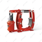
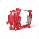
YWZ8-700/E301 Electro-hydraulic Drum Brakes
Installation and Use of the YWZ8-700/E301 Electro-hydraulic Drum Brake 1. System Overview The YWZ8-700/E301 is a spring-applied, hydraulically released (SAHR) external drum brake system , designed for heavy-duty industrial applications. The system consists of two main components: YWZ8-700...
Description
Installation and Use of the YWZ8-700/E301 Electro-hydraulic Drum Brake
1. System Overview
The YWZ8-700/E301 is a spring-applied, hydraulically released (SAHR) external drum brake system, designed for heavy-duty industrial applications. The system consists of two main components:
YWZ8-700 Brake Caliper: A mechanical assembly that clamps onto a 700 mm diameter brake drum.
E301 Electro-hydraulic Thruster: A self-contained hydraulic power unit that supplies pressure to release the brake. The /E301suffix indicates the specific thruster model paired with the caliper.
This modular design allows flexible mounting and is engineered for fail-safe operation-the brake engages automatically upon power loss or system failure.
2. Installation Procedure
Safety Precautions:
Lockout/Tagout (LOTO): Isolate all electrical and hydraulic power sources before installation.
Qualified Personnel: Installation must be performed by trained technicians adhering to local mechanical, electrical, and safety codes.
Inspection: Check all components (caliper, thruster, hydraulic lines, drum) for damage or contamination before assembly.
A. Mechanical Installation of the Brake Caliper (YWZ8-700)
Drum Preparation:
Ensure the brake drum diameter is exactly 700 mm. The drum surface must be clean, concentric, and free of oil, grease, or rust.
Verify drum runout and surface roughness are within manufacturer tolerances (typically ≤0.1 mm runout).
Mounting the Caliper:
Secure the caliper's baseplate to a rigid, vibration-free structure (e.g., machine frame or crane girder) using high-strength foundation bolts.
Alignment is critical:
a. Center the caliper symmetrically relative to the drum's vertical axis.
b. Align the brake shoes parallel to the drum surface.
c. Set an initial uniform air gap of 1.0–1.5 mm between each shoe and the drum (use feeler gauges at multiple points). Adjust via the eccentric pivot pins or handwheel on the caliper.
Torque Fasteners:
Tighten all mounting bolts evenly in a crisscross pattern to the specified torque (refer to manual-typically 300–450 Nm for M20 bolts).
B. Installing the Electro-hydraulic Thruster (E301)
Mounting the Thruster:
Mount the E301 thruster on a stable surface near the brake, ensuring adequate space for maintenance and heat dissipation.
Use flexible mounts or dampers if vibration is expected.
Mechanical Linkage:
Connect the thruster's push rod to the brake caliper's release lever using the provided clevis pin and securing clips.
Ensure the linkage moves freely without binding. The lever ratio determines the mechanical advantage-verify it matches design specifications.
Hydraulic System Setup:
Fill the thruster with the recommended hydraulic fluid (e.g., ISO VG 32 or anti-wear hydraulic oil) to the marked level.
Bleed air completely:
a. Operate the thruster briefly while slightly loosening the hydraulic fittings at the highest points.
b. Tighten fittings once fluid flows without bubbles.
c. Repeat until the push rod extends/retracts smoothly without "spongy" behavior.
C. Electrical Connections
Wire the E301 thruster motor to a 3-phase AC power supply (e.g., 400 V, 50 Hz) via a dedicated contactor and overload protection.
Connect the control circuit to the thruster motor terminals, ensuring proper sequencing (thruster must energize before the drive motor starts).
For systems with multiple brakes, use synchronized control to avoid uneven loading.
3. Adjustment, Commissioning, and Running-In
A. Final Adjustments
Air Gap Calibration:
With the thruster de-energized, confirm the shoes contact the drum fully.
Energize the thruster and measure the final air gap (typically 1.5–2.0 mm per side). Adjust the thruster's stroke limiter or linkage length if needed.
Braking Torque Adjustment:
Adjust the preload of the main compression spring(s) on the caliper to achieve the required braking torque (see manual for torque specs).
Caution: Do not over-tighten-excessive spring force can overload the thruster.
Shoe Alignment ("Toe-In"):
Set a slight toe-in (0.2–0.5 mm tighter clearance at the leading shoe edge) to prevent squeal and ensure even wear. Use eccentric pivot pins for fine-tuning.
B. Running-In Procedure
Perform 20–30 gentle, low-energy stops at ≤20% of rated load to seat the linings.
Avoid prolonged dragging or high-temperature braking during run-in.
4. Normal Operation and Safety Features
Operating Principle:
Release: When energized, the E301 thruster's motor drives a hydraulic pump, extending the push rod to compress the brake spring and retract the shoes.
Running: The brake stays released as long as the thruster is powered.
Fail-Safe Application: Upon power loss, the spring forcibly re-engages the brake. The hydraulic fluid returns to the reservoir, and the shoes clamp the drum within 0.1–0.3 seconds.
Critical Usage Notes:
This is a holding/emergency brake, not a service brake. Do not use for frequent cycling or speed control.
Monitor the thruster's duty cycle (e.g., max 60% for E301)-overuse causes overheating.
The brake must only engage at near-zero speed to avoid excessive wear.
5. Maintenance and Inspection
Daily/Weekly Checks:
Verify no abnormal noises or leaks.
Check hydraulic fluid level in the thruster.
Ensure the brake releases/engages fully without delay.
Monthly/Quarterly Inspections:
Lining Wear: Measure lining thickness. Replace both shoes if wear exceeds 30% of original thickness.
Air Gap: Recheck and adjust to compensate for lining wear.
Pivots & Linkage: Lubricate all pins, bushings, and bearings (use high-temperature lithium grease). Keep grease off linings and drum.
Hydraulic System: Inspect hoses/fittings for leaks. Replace fluid per manufacturer intervals (typically 1–2 years).
Annual Overhaul:
Disassemble, clean, and inspect all components.
Replace seals, worn pins, and linings as needed.
Test braking torque with a calibrated torque wrench.
6. Troubleshooting Common Issues
|
Symptom |
Possible Cause |
Solution |
|---|---|---|
|
Slow release/application |
Air in hydraulic system |
Re-bleed system; check for leaks |
|
Reduced braking torque |
Worn linings; low spring preload |
Replace linings; adjust spring tension |
|
Overheating thruster |
Excessive cycling; low fluid |
Check duty cycle; top up fluid |
|
Uneven shoe wear |
Misalignment; drum runout |
Re-align caliper; machine drum |
Summary
The YWZ8-700/E301 is a robust, fail-safe braking system for heavy machinery. Successful installation depends on precise caliper-drum alignment and proper hydraulic bleeding. Its reliability hinges on strict adherence to duty cycle limits, regular air-gap adjustments, and preventive maintenance. Always prioritize the manufacturer's official manual for model-specific tolerances, torque values, and safety warnings.
Note: The E301 thruster specifications (e.g., thrust force, motor power) may vary. Confirm actual parameters from the product datasheet.
Hot Tags: ywz8-700/e301 electro-hydraulic drum brakes, China, manufacturers, supplier, factory, customized
You Might Also Like