

Latest Products


Contact Us
- Wei Four Road, Weizhuang industrial Park, Changyuan District, Xinxiang City, Henan Province, China
- sales@zybc.com
- +86-373-7136666


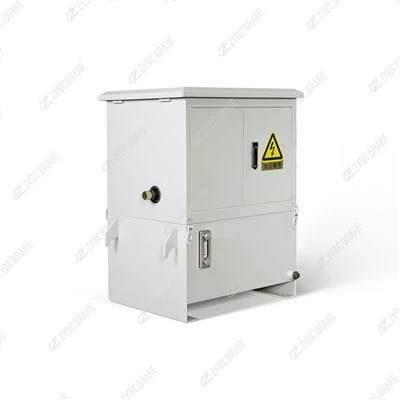
YZA20-8 Series Hydraulic Power Unit
The YZA20-8 series hydraulic power unit is a compact, integrated hydraulic system designed to provide stable pressure and flow for industrial braking, clamping, and lifting mechanisms (e.g., matching YFX wedge brakes, YLZ wheel brakes, and rail clamps). It features a small footprint, low noise,...
Description
The YZA20-8 series hydraulic power unit is a compact, integrated hydraulic system designed to provide stable pressure and flow for industrial braking, clamping, and lifting mechanisms (e.g., matching YFX wedge brakes, YLZ wheel brakes, and rail clamps). It features a small footprint, low noise, and reliable operation, suitable for outdoor port, crane, and metallurgical equipment. Below is a detailed overview of its core parameters, structural features, working principle, maintenance guidelines, and common faults & solutions.
Core Technical Parameters
| Parameter | Standard Value | Notes |
|---|---|---|
| Rated working pressure | 20 MPa | Max pressure for continuous operation |
| Rated flow | 8 L/min | Flow output at rated pressure |
| Motor power | 3 kW | 3-phase AC 380V/50Hz, IP55 protection |
| Tank capacity | 40 L | Integrated oil tank with level gauge |
| Hydraulic oil type | ISO VG46 anti-wear hydraulic oil | Low-temperature ISO VG32 optional for -25℃ environments |
| Working medium temperature | -20℃ to +55℃ | Oil temp must not exceed 60℃ during operation |
| Control voltage | AC 220V/DC 24V | For solenoid valve actuation |
| Protection features | Overpressure relief, oil level alarm, overheat protection | Safety interlock with host equipment |
| Weight | ~120 kg | Compact integrated design |
| Compliance standard | GB/T 3766-2015 (Hydraulic system general requirements) |
Key Structural Features
Integrated Modular Design
Combines motor, gear pump, oil tank, solenoid valve block, relief valve, filter, and pressure gauge into one unit, eliminating external pipelines and reducing leakage risks.
The solenoid valve block integrates directional control valves, check valves, and throttle valves, enabling precise control of oil flow direction and speed for connected actuators (e.g., brake cylinders, rail clamp jaws).
Multi-Level Safety Protection
Overpressure relief valve: Automatically unloads when pressure exceeds 22 MPa (10% above rated pressure) to protect the pump and pipeline from burst damage.
Oil level sensor: Triggers an alarm when oil level drops below the MIN mark, preventing pump cavitation.
Oil temperature sensor: Shuts down the motor if oil temp exceeds 65℃, avoiding oil deterioration and seal aging.
High-Efficiency Filtration System
Equipped with a suction filter (100 μm) and return filter (25 μm) to remove impurities from the oil circuit, extending the service life of valves and pumps.
The return filter has a pressure difference indicator-when the indicator turns red, the filter element must be replaced immediately.
Easy Maintenance & Installation
Transparent oil level gauge and drain plug for quick oil level checks and oil changes.
Flange-mounted design for direct installation on the host equipment frame; oil outlet/inlet ports use standard threaded connections for easy matching with actuators.
Working Principle
The YZA20-8 series operates as a constant-pressure supply system for brake/rail clamp hydraulic actuators, with three core working states:
Pressure Build-Up State (Release Brake/Rail Clamp)
When the host equipment (e.g., crane) needs to start, the control system sends a signal to energize the solenoid valve.
The motor drives the gear pump to draw oil from the tank, pressurize it to 20 MPa, and deliver it to the actuator (e.g., brake cylinder). Hydraulic pressure pushes the piston to release the brake/rail clamp.
When pressure reaches the rated value, the pressure switch sends a signal to stop the motor (or switch to pressure-holding mode) to save energy.
Pressure-Holding State (Equipment Operation)
The check valve in the solenoid valve block maintains pressure in the actuator circuit, ensuring the brake/rail clamp remains released during equipment operation.
If pressure drops due to minor leakage, the pressure switch triggers the motor to restart and replenish pressure automatically.
Unloading State (Braking/Clamping)
When the host equipment stops, the solenoid valve de-energizes, and the oil circuit is connected to the tank.
Hydraulic oil in the actuator flows back to the tank under the action of the brake's disc spring or rail clamp's clamping spring, and the actuator resets to achieve braking/clamping.
Maintenance Guidelines
1. Daily Inspection (5–10 Minutes/Shift)
Oil Level & Quality Check: Confirm oil level is between MAX and MIN marks; check oil color (clear amber is normal-dark/turbid oil indicates contamination and needs replacement).
Pressure & Leakage Check: Observe the pressure gauge-pressure should stabilize at 20 MPa during operation; inspect all pipe joints, valve block interfaces, and oil seals for oil drips (tighten loose joints immediately).
Electrical System Check: Inspect motor cables, solenoid valve wiring, and sensor connections for fraying or loosening; verify the oil level/oil temp alarm works normally.
Filter Indicator Check: Ensure the return filter indicator is green (red = blocked filter element, needs replacement).
2. Periodic Maintenance Schedule
| Maintenance Cycle | Core Tasks | Details & Standards |
|---|---|---|
| 1 Month | Filter Cleaning & Fastener Tightening | - Clean the suction filter screen (remove and rinse with clean hydraulic oil);- Re-tighten mounting bolts and pipe joint nuts (torque: 30–40 N·m for M12 bolts). |
| 3 Months | Oil Replacement & System Bleeding | - Drain old oil, flush the tank with clean ISO VG46 oil, and refill to the MAX mark;- Bleed air from the system: Run the unit at no-load for 5 minutes, then cycle the solenoid valve 3–5 times to expel trapped air (air causes pressure instability). |
| 6 Months | Filter Element & Seal Replacement | - Replace the return filter element (25 μm);- Inspect and replace aging O-rings and seals in the valve block and pipe joints to prevent leakage. |
| 12 Months | Comprehensive Overhaul | - Disassemble the gear pump and check for wear on gears and bearings (replace if clearance exceeds 0.1 mm);- Calibrate the relief valve to ensure it unloads at 22 MPa;- Test the oil level/oil temp sensors and pressure switch for accuracy;- Clean the tank interior to remove sediment and impurities. |
3. Special Environment Maintenance
High-Dust/Coastal Environments: Install a dust cover on the motor and oil tank; apply anti-rust oil to the unit surface monthly; shorten filter replacement cycles to 4 months.
Low-Temperature Environments (-20℃ to 0℃): Replace ISO VG46 oil with low-temperature ISO VG32 oil; preheat the unit for 10 minutes before operation to reduce oil viscosity.
Common Faults & Solutions
| Fault Phenomenon | Possible Causes | Step-by-Step Solutions | Preventive Measures |
|---|---|---|---|
| No pressure output (actuator fails to release) | 1. Low oil level or oil suction blockage;2. Motor reversed or power supply failure;3. Gear pump worn or damaged;4. Solenoid valve not energized or stuck. | 1. Refill oil to MAX mark; clean the suction filter;2. Check motor wiring to correct rotation direction; test power supply voltage (380V ±10%);3. Disassemble the pump and replace worn gears/bearings;4. Check solenoid valve coil voltage; disassemble and clean valve core to remove jamming impurities. | - Check oil level daily;- Protect motor cables from damage;- Replace filter elements on schedule. |
| Pressure unstable (fluctuates between 10–20 MPa) | 1. Air trapped in the system;2. Relief valve stuck or adjusted improperly;3. Return filter blocked;4. Pipe joint leakage. | 1. Bleed air by running no-load and cycling the solenoid valve;2. Clean the relief valve core; recalibrate to unload at 22 MPa;3. Replace the blocked return filter element;4. Tighten pipe joints and replace damaged seals. | - Bleed air after oil replacement;- Clean the relief valve quarterly;- Monitor filter indicator daily. |
| Motor overheating (surface temp >80℃) | 1. Long-term pressure-holding operation;2. Oil viscosity too high (low temp) or too low (high temp);3. Motor bearing wear or ventilation blocked;4. Overpressure relief valve failure (pump runs continuously at high pressure). | 1. Optimize control logic to reduce pressure-holding time;2. Replace with ISO VG46 oil (match ambient temp);3. Replace motor bearings; clean dust from motor ventilation holes;4. Repair or replace the relief valve. | - Monitor oil temp (<60℃);- Clean motor vents monthly;- Calibrate relief valve annually. |
| Oil leakage at valve block/pipe joints | 1. Seal/O-ring aging or damaged;2. Joint nuts loose;3. Valve block interface deformation due to vibration. | 1. Replace aging seals with oil-resistant nitrile rubber parts;2. Re-tighten joint nuts with torque wrench (avoid over-tightening);3. Install shock-absorbing gaskets under the valve block to reduce vibration. | - Replace seals every 6 months;- Check joint tightness monthly;- Install shock absorbers for high-vibration equipment. |
Safety Precautions
Lockout-Tagout Before Maintenance: Cut off the power supply and hang a "No Operation" warning sign; release all pressure in the system by opening the unloading valve before disassembling components.
Oil Compatibility: Use only ISO VG46 anti-wear hydraulic oil-mixing different brands or types will cause seal hardening and system failure.
Overpressure Prohibition: Do not adjust the relief valve to exceed 22 MPa; this will damage the pump and pipeline.
Alarm Response: Stop the unit immediately when the oil level/oil temp alarm is triggered-do not continue operation to avoid pump burnout.
Hot Tags: yza20-8 series hydraulic power unit, China, manufacturers, supplier, factory, customized
You Might Also Like


