Latest Products


Contact Us
- Wei Four Road, Weizhuang industrial Park, Changyuan District, Xinxiang City, Henan Province, China
- sales@zybc.com
- +86-373-7136666


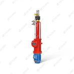
DYTZWB1000-400/50P K1.F Electro-Hydraulic Pusher: Working Principle And Applications
DYTZWB1000-400/50P K1.F Electro-Hydraulic Pusher: Working Principle and Applications The DYTZWB1000-400/50P K1.F is a heavy-duty forced-cooled model in the DYT series of electro-hydraulic pushers. It features an ultra-large rated thrust of 1000 kN and a long stroke of 400 mm, with a...
Description
DYTZWB1000-400/50P K1.F Electro-Hydraulic Pusher: Working Principle and Applications
The DYTZWB1000-400/50P K1.F is a heavy-duty forced-cooled model in the DYT series of electro-hydraulic pushers. It features an ultra-large rated thrust of 1000 kN and a long stroke of 400 mm, with a flange-mounted design. It is specifically engineered to meet the linear drive and brake control needs of extra-heavy industrial equipment. Its working principle revolves around the efficient conversion of "electrical energy - hydraulic energy - mechanical force," with applications concentrated in extreme working conditions such as large-scale hoisting, metallurgy, and mining. Details are as follows:
I. Working Principle
The pusher adopts the core logic of "high-power motor-driven hydraulic system + high-pressure spring reset," integrated with forced cooling and pressure stabilization designs. The working process is divided into two core stages: power-on extension (thrust output) and power-off retraction (reset braking), supplemented by multiple safety mechanisms to ensure stable operation:
1. Power-On Extension Stage (Thrust Output)
When connected to 380V three-phase AC power, the 50 kW high-power asynchronous motor starts, driving the built-in high-pressure gear pump to rotate at high speed.
The gear pump draws ISO VG68 high-temperature resistant and anti-wear hydraulic oil from the large-capacity oil tank (≥50 L), pressurizes it to 25–31.5 MPa, and delivers it to the double-acting reinforced cylinder via high-pressure oil pipes (burst pressure ≥95 MPa).
Hydraulic pressure pushes the piston and chrome-plated alloy steel push rod in the cylinder to extend linearly, stably outputting a rated thrust of 1000 kN within a 400 mm stroke. Force is transmitted to the supporting heavy-duty mechanism (e.g., large brake connecting rod, clutch engagement device) through flange connectors, completing actions such as brake release or mechanism activation.
Simultaneously, the forced air cooling fan (power 1.5 kW) at the motor end starts synchronously, combined with a plate-type oil cooler (cooling area ≥2 m²), controlling the operating temperature of the motor and hydraulic system within 85°C to meet the demand for long-term continuous operation.
The rated extension time is ≤3.5 seconds, enabling rapid response to the operation signals of extra-heavy equipment.
2. Power-Off Retraction Stage (Reset Braking)
When the power is cut off or the control signal is terminated, the motor stops running, the hydraulic pump ceases oil supply, and the built-in high-pressure relief valve (maximum pressure ≤35 MPa) opens to relieve pressure. Hydraulic oil flows back to the oil tank through the cooling oil circuit.
Multiple sets of stacked disc springs made of 60Si2MnA alloy steel in the cylinder (total stiffness ≥200 kN/mm) release elastic force, pulling the piston and push rod to retract quickly to their initial positions, and the thrust is fully released.
The supporting heavy-duty brake or control mechanism resets under its own spring force, realizing the braking and locking of extra-heavy equipment. The rated retraction time is ≤2.8 seconds, ensuring rapid and safe response in emergency situations.
3. Stability & Safety Guarantee Designs
A pressure compensator maintains system pressure fluctuation ≤±2%, ensuring stable thrust output when the load changes. The motor adopts H-class insulation and is equipped with a thermal protector, which automatically cuts off power when the temperature exceeds 180°C to avoid overload burnout.
A 5 μm high-precision oil suction filter and optimized oil circuit design prevent cavitation. Multi-layer FKM high-pressure seals (pressure resistance ≥40 MPa) eliminate oil leakage and extend the service life of the hydraulic system.
An integrated position sensor with IP67 protection rating outputs "extended in place" and "retracted in place" signals, achieving interlock control with the host equipment (the host can only start after the pusher is in place) to avoid misoperation.
II. Typical Applications
This product is specifically designed for 500–5000 ton class extra-heavy industrial equipment, adapting to extreme working conditions such as high temperature, heavy dust, and high vibration. Core application scenarios are as follows:
1. Large-Scale Hoisting & Port Machinery
Compatible with the main brake release mechanism of 1000–5000 ton class port gantry cranes and container quay cranes. It provides stable thrust during the hoisting of heavy containers, resisting sea breeze and load impact, and ensuring precise and controllable brake release.
Used in the brake and clutch drive system of heavy-duty cranes in shipyards (e.g., hull section cranes). The 400 mm long stroke matches the large displacement demand of the crane's connecting rod mechanism, guaranteeing the positioning accuracy of hull component hoisting.
2. Metallurgical & Steel Mill Machinery
Drives the locking and release mechanisms of steelmaking converters (above 300 tons) and ladle transfer cars in steel mills. It withstands the high temperature (≤100°C) and heavy dust environment of steel mills, ensuring stable positioning during ladle transfer and preventing molten steel leakage.
Controls the brake system of billet conveyors and coil handling equipment in large steel rolling mills. Stable thrust output avoids material spillage or equipment jamming, adapting to high-frequency start-stop working conditions (up to 200 times per hour).
3. Mining & Heavy-Duty Transport Machinery
Serves as the main brake release drive component for 500–1000 ton class mine hoists and inclined shaft conveyors. It adapts to the humid and dusty underground or open-pit mine environment. The rapid reset performance (≤2.8 seconds) can achieve emergency braking in case of sudden power failure, preventing ore spillage or hoist runaway.
Drives the brake and positioning mechanisms of extra-heavy rail transfer cars (e.g., large equipment component transporters) in industrial parks. The 1000 kN thrust ensures reliable locking of the vehicle on flat or slightly inclined rails, avoiding load displacement.
4. Hydropower & Engineering Construction Machinery
Used for the opening and closing drive of sluice gates in large hydropower stations, adapting to the lifting needs of ≥1000 ton class gates. The 400 mm stroke matches the gate displacement, and the pressure-resistant design can resist water flow impact, ensuring stable gate operation.
Provides power for the auxiliary brake and positioning mechanisms of large Tunnel Boring Machines (TBMs). It withstands the high-vibration and heavy-dust environment in tunnels, and the forced cooling system ensures continuous and stable operation during long-duration tunnel excavation.
Hot Tags: dytzwb1000-400/50p k1.f electro-hydraulic pusher: working principle and applications, China, manufacturers, supplier, factory, customized, hoist safety crane brake, Electro Hydraulic Thruster Disc Brakes
You Might Also Like