
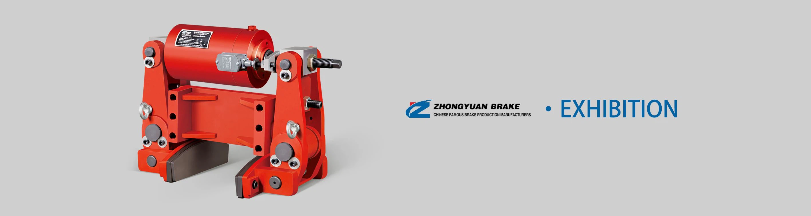
1. Model Interpretation & Core Function
The YWZ8-160/E23A's model code directly reflects its design upgrades, matching components, and performance scope, enabling quick equipment pairing:
| Model Segment | Meaning |
|---|---|
| YWZ8-A | Upgraded 8th-Generation Drum Brake Series ("A" = enhanced corrosion resistance, modular design, dedicated thruster compatibility) |
| 160 | Brake drum diameter: 160 mm (medium-sized drum for light-to-medium loads) |
| E23A | Matched dedicated electro-hydraulic thruster: E23 variant ("A" = optimized for YWZ8-A series' lever layout and mounting points) |
Its core functions target high-reliability safety and efficiency for medium-duty machinery, addressing upgraded industrial demands:
High-Frequency Braking: Smoothly decelerates or stops machinery during frequent start-stop cycles (e.g., logistics conveyors, intermittent winches) without thermal fading.
Emergency Stopping: Rapidly engages in power loss, thruster failure, or overspeed (≥110% of rated speed) to prevent machinery runaway and avoid material spillage or equipment damage.
Static Load Holding: Secures medium loads (e.g., 3–12 ton lifted goods, conveyor materials) during downtime, maintenance, or power outages-ensuring zero accidental movement.
Corrosion-Resistant Operation: Adapts to humid, dusty, or mild corrosive environments (e.g., coastal logistics yards, cement plants) via A-type anti-corrosion upgrades.
2. Working Principle
The YWZ8-160/E23A operates on a fail-safe principle (spring force for braking, electro-hydraulic thrust for release), inheriting the YWZ8 series' heat management advantages while optimizing force transmission for A-type upgrades. Its working cycle includes three key states:
2.1 Brake Engagement (Safety State)
When the machinery is stationary, in emergency, or powered off, internal high-tension compression springs (60Si2MnA alloy steel) expand outward.
The springs push two arc-shaped brake shoes to swing outward, pressing the high-temperature-resistant friction pads tightly against the inner wall of the rotating brake drum.
Friction between the pads and drum generates stable braking torque (200–320 N·m), which resists the drum's rotation-either stopping the connected shaft or holding it stationary.
2.2 Brake Release (Operating State)
When the machinery needs to run, the matched E23A electro-hydraulic thruster is activated. The thruster converts electrical energy into linear hydraulic thrust (230 N) via its internal centrifugal pump and cylinder.
This thrust pulls the integrated modular lever mechanism (A-type optimization), compressing the internal springs and retracting the brake shoes inward. A precise 0.3–0.6 mm clearance is created between the pads and drum-minimizing drag friction and energy loss.
The brake drum rotates freely with the machinery shaft, enabling normal operation (e.g., conveyor movement, winch lifting).
2.3 Emergency Response (Fault State)
In case of power loss, thruster oil leakage, or emergency shutdown, the thruster's thrust dissipates instantly.
The compressed springs rebound within ≤0.3 seconds, driving the brake shoes to re-clamp the drum-engaging the brake rapidly to stop the machinery and eliminate safety hazards.


