
Latest Products


Contact Us
- Wei Four Road, Weizhuang industrial Park, Changyuan District, Xinxiang City, Henan Province, China
- sales@zybc.com
- +86-373-7136666


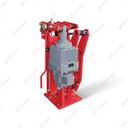
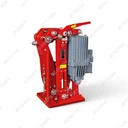
YWZ9-300/E50 Electro-Hydraulic Drum Brake: Advantages, Working Principle & Installation
The YWZ9-300/E50 is a heavy-duty electro-hydraulic drum brake from the YWZ9 series, integrated with the E50 electro-hydraulic thruster as its core drive component. It features a 300 mm drum diameter, 2000–3150 N·m adjustable braking torque, and a normally closed safety...
Description
The YWZ9-300/E50 is a heavy-duty electro-hydraulic drum brake from the YWZ9 series, integrated with the E50 electro-hydraulic thruster as its core drive component. It features a 300 mm drum diameter, 2000–3150 N·m adjustable braking torque, and a normally closed safety design-optimized for heavy-load industrial equipment requiring reliable braking. Widely used in cranes, hoists, conveyors, and metallurgical machinery, it combines high torque output, durable structure, and user-friendly operation. Details are as follows:
1. Core Advantages
1.1 Superior Safety & Fail-Safe Performance
Adopts a normally closed design relying on high-tension disc springs (60Si2MnA alloy steel) to maintain braking state when de-energized. In case of sudden power failure, hydraulic system malfunction, or thruster breakdown, it automatically engages braking within ≤0.5 seconds, preventing equipment runaway and heavy-load slipping. The E50 thruster is equipped with F-class insulation and a thermal protector (cuts off power at 155°C), avoiding motor burnout due to overload or prolonged operation.
1.2 Stable & High Torque Braking
Boasts a 300 mm diameter brake drum (width: 100 mm) and asbestos-free high-temperature resistant friction linings (friction coefficient μ ≥ 0.45). The linings withstand -20°C to 200°C and are insensitive to moisture, dust, or mild corrosion, ensuring consistent braking torque (2000–3150 N·m) in harsh industrial environments. The drum's double-sided heat dissipation structure reduces thermal deformation, avoiding brake fade during high-frequency, long-term operation.
1.3 Durable & Low Maintenance
Equipped with imported FKM high-pressure seals and a fully sealed brake body, effectively preventing dust, moisture, and corrosive substances from entering internal components. The brake drum (forged 42CrMo steel) and friction linings have a service life of ≥20,000 working hours. A built-in automatic wear compensation mechanism eliminates manual clearance adjustment, reducing maintenance frequency and downtime.
1.4 Compact & Versatile Integration
Integrates the brake body and E50 thruster into a modular structure (net weight ≈120 kg), saving installation space compared to split-type designs. It adapts to brake discs of 25–35 mm thickness and is compatible with heavy-load equipment (50–150 tons). The E50 thruster supports 380V three-phase AC (optional 220V AC) and standardized hydraulic interfaces, simplifying connection to existing systems.
1.5 Precise & Adjustable Control
The E50 thruster's hydraulic pressure (12–16 MPa) is adjustable, allowing stepless regulation of braking torque to match different load requirements. Optional limit switches (for release and wear status) enable interlock control with the host PLC, realizing real-time fault monitoring and early warning.
2. Working Principle
The brake operates through the coordination of "electro-hydraulic thrust (E50 thruster) and disc spring force," following a normally closed logic:
2.1 Brake Release (Power-On Stage)
When the host equipment needs to run, the E50 thruster is energized. Its built-in motor (rated power: 2.2 kW) drives the hydraulic pump to generate 12–16 MPa pressure, pushing the thruster's push rod (rated stroke: 50 mm) to extend linearly.
The push rod transmits force to the brake's lever mechanism, compressing the high-tension disc springs and driving the two brake shoes to separate outward from the drum.
A 0.3–0.5 mm uniform clearance is formed between the linings and drum, allowing the drum to rotate freely with the equipment's rotating shaft-completing the release action.
2.2 Braking Engagement (Power-Off Stage)
When the equipment stops or an emergency occurs, the thruster is de-energized. The hydraulic system relieves pressure, and the thruster's push rod retracts under its internal return spring force.
The disc springs rebound rapidly, pushing the brake shoes to clamp inward toward the rotating drum. Friction between the linings and drum generates rated braking torque, decelerating the equipment until it stops and maintaining a locked state.
3. Installation Specifications
3.1 Pre-Installation Preparation
Bracket & Base Requirements: The mounting bracket (not supplied) must be manufactured to match the product manual's dimensions, tolerances, and surface roughness. The base should be welded or bolted to a rigid structure (flatness deviation ≤0.2 mm/m) to avoid vibration during braking.
Component Inspection: Check for damage to the brake body, drum, linings, springs, and thruster. Verify the E50 thruster's oil level (ISO VG46 anti-wear hydraulic oil) and seal integrity (no leakage). Ensure the hydraulic system's oil cleanliness ≤ NAS 8.
Tool Preparation: Prepare a torque wrench (0–500 N·m), caliper gauge, level meter, 10.9-grade high-strength bolts (M16/M20) with nylon lock inserts, and quenched/tempered 45# steel flat washers.
3.2 Core Installation Steps
Positioning & Alignment: Align the brake body with the drum, ensuring the brake shoes are symmetrically distributed. The initial clearance between linings and drum should be 2–3 mm on both sides; adjust via the thruster's push rod if needed.
Securing the Brake: Fasten the brake body to the bracket using 8 or more 10.9-grade bolts. Tighten in a diagonal sequence to the specified torque (220–250 N·m) for M16 bolts or 350–400 N·m for M20 bolts, ensuring uniform clamping force.
Thruster & Hydraulic Connection: Fix the E50 thruster to the brake's lever mechanism (coaxiality deviation ≤0.8 mm). Connect the thruster's hydraulic inlet/outlet to the system using high-pressure hoses (burst pressure ≥45 MPa), seal threads with thread sealant, and bleed air from the circuit.
Electrical Wiring: Wire the E50 thruster to the power supply according to the wiring diagram, ensuring tight and insulated connections to avoid short circuits.
3.3 Installation Precision Control
Drum Runout: Maximum end runout ≤±0.3 mm; radial runout ≤±0.2 mm.
Perpendicularity & Centering: Base perpendicularity deviation relative to the drum axis ≤±3‰; drum centering deviation relative to the brake center ≤±3 mm.
Lever Mechanism: Ensure no jamming in hinges; apply high-temperature lubricating grease to moving parts.
3.4 Post-Installation Calibration & Testing
Action Test: Energize the thruster to verify smooth release (clearance: 0.3–0.5 mm) and engagement without abnormal noise or jamming.
Torque Verification: Conduct a load test to confirm braking torque meets the required range (2000–3150 N·m); adjust hydraulic pressure if necessary.
Safety Test: Simulate power failure to verify automatic braking within ≤0.5 seconds. Check the thruster's thermal protection and ensure no oil leakage during 1-hour continuous operation.
Hot Tags: ywz9-300/e50 electro-hydraulic drum brake: advantages, working principle & installation, China, manufacturers, supplier, factory, customized, durable crane drum brake, Electro Hydraulic Thrustor Brake, Hydraulic Operated Brakes, Port handling drum brake, Port machinery Disc brake, riveted type crane drum brake
You Might Also Like


