Latest Products


Contact Us
- Wei Four Road, Weizhuang industrial Park, Changyuan District, Xinxiang City, Henan Province, China
- sales@zybc.com
- +86-373-7136666


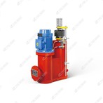
DYT Series Electro-hydraulic Pusher: Installation Methods & Matching Accessories
DYT electro-hydraulic pushers adopt horizontal installation as standard; vertical/inclined mounting is available for special modified models. Standard supporting accessories include front/rear hinge joints and waterproof wiring glands; sealing repair kits and dedicated hydraulic oil are regular consumable spares. Flameproof assemblies, extended push rods, stroke limit brackets and dustproof shields are optional supporting parts applicable to gates, conveyors, material baffles and other industrial linear adjustment equipment.
Description

DYT SERIES electro-hydraulic pusher
DYT electro-hydraulic pushers adopt horizontal installation as standard; vertical/inclined mounting is available for special modified models. Standard supporting accessories include front/rear hinge joints and waterproof wiring glands; sealing repair kits and dedicated hydraulic oil are regular consumable spares. Flameproof assemblies, extended push rods, stroke limit brackets and dustproof shields are optional supporting parts applicable to gates, conveyors, material baffles and other industrial linear adjustment equipment.
Products Description
1. Installation Methods
DYT series electro-hydraulic pushers are linear drive actuators widely used for gate opening/closing, baffle adjustment, conveyor tensioning and auxiliary brake actuation. Horizontal mounting is the standard layout, vertical upward/vertical downward inclined installation can be customized per site conditions. Mounting lugs conform to general industry connection dimensions for convenient interchange.
Standard Horizontal Installation
Secure the front hinge base and rear mounting support to rigid fixed frames with high-strength anti-loose bolts. Ensure the central axis of the pusher piston rod is horizontal without bending or offset stress.
Connect the front end of the push rod to the driven equipment hinge joint via pin shaft; leave reasonable stroke margin to avoid mechanical top dead point impact or insufficient travel.
Arrange the motor housing on the upper side of the cylinder body to ensure the built-in hydraulic oil fully immerses internal pump and transmission parts, preventing air trapping and slow response.
Reserve sufficient space around the cylinder for oil filling, seal replacement and stroke maintenance inspection.
Optional Vertical & Inclined Installation
Vertical upward mounting: Add auxiliary oil retaining baffles inside customized oil tanks to avoid oil starvation during operation.
Vertical downward / inclined mounting (≤75° tilt angle): Must select DYT special tilted version; standard horizontal DYT cannot be installed upside down directly, otherwise internal parts will suffer dry friction damage.
After non-horizontal assembly, recheck the oil level against the sight glass mark and supplement dedicated hydraulic oil as required.
Core Installation & Commissioning Requirements
All hinge pin joints are equipped with self-lubricating sleeves; apply lithium-based grease during assembly.
Before power test, fill specified anti-wear hydraulic oil to the calibrated liquid level on the sight glass; overfilling or underfilling causes jitter and abnormal noise.
Install travel limit switches at both full extension and full retraction positions to realize stroke protection and position feedback.
Standard power supply: AC380V; AC220V single-phase motor variants are available for small-size models.
Isolate the motor cylinder from splash water, heavy dust and corrosive gas to extend coil and seal service life.
Do not apply lateral radial load on the piston rod during operation to prevent rod bending and seal abrasion.
2. Standard Matching Accessories
Core Functional Supporting Components
Front & Rear Hinge Joint AssemblyIncluding articulated ear bases, connecting pins, cotter pins and wear-resistant bushings for linking the pusher to driven machinery.
Waterproof Junction Box & Cable GlandBuilt-in wiring terminals matched with sealed cable connectors to block water and dust from entering the motor cavity.
Stroke Adjustment Lock NutsAdjust effective extension length of the push rod and lock the target working stroke.
Built-in Overload Relief ValveStandard integrated component to automatically release pressure when encountering overload, protecting cylinder and motor from damage.
Consumable Spare Parts
Complete Cylinder Sealing Repair KitContains piston oil seals, dust-proof rod rings, end cover gaskets and O-rings for solving hydraulic oil leakage faults.
Special Electro-Hydraulic OilLow-temperature anti-wear hydraulic fluid for periodic oil replacement maintenance.
Motor Spare ComponentsReplacement stator coils, hydraulic pump impellers and rolling bearings for motor burnout or pump jamming repair.
Liquid Level Sight GlassTransparent observation window for real-time monitoring of internal oil volume.
3. Optional Custom Accessories
Flameproof motor assemblies and Ex-certified limit switches for coal mines, chemical plants and flammable explosive hazardous areas.
Extended customized piston rods for equipment requiring ultra-long working strokes.
External travel limit switch bracket set for accurate stroke positioning and interlock control.
Rainproof dustproof integrated protective outer housing for open-air ports, metallurgy and cement plant harsh environments.
Buffer damping sleeves to reduce mechanical impact at full stroke limit positions.
Anti-corrosion coated cylinder body and stainless steel connecting fasteners for coastal salt fog, humid corrosive workshops.
Manual emergency hand pump set for manual push rod retraction when power supply fails.
Hot Tags: dyt series electro-hydraulic pusher: installation methods & matching accessories, China, manufacturers, supplier, factory, customized
You Might Also Like